3.2.2. Lab 2: Executing the playbooks
3.2.2.1. iWorflow
Let’s login to iWorkflow and have a look at the configuration before we run the playbook
Let us first execute the playbook on iWorkflow. This playbook will perform the following tasks
- Discover device
- Create a cloud connector
- Create a service template – Parameters than are tenant editable on
this template are
- Virtual IP
- Virtual Port
- Load balancing method
- Pool members
To execute the playbook run command:
SSH to the “Tools” host
Go to the
/rootdirectoryansible-playbook --step playbooks/iworkflow_setup.yamlNote
The playbook will be run step by step, after the first task device discovery, make sure before you go to the next step the device is discovered correctly and the BIG-IP is in a healthy state
The following gets created on iWorkflow after playbook(
iworkflow_setup.yaml) execution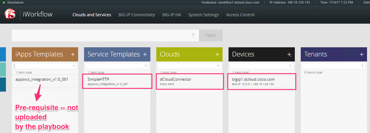
Once executed the playbook downloads the device package to the playbooks directory. Open WinSCP again and move this downloaded device package to desktop on your dcloud environment. Name of the device package is picked up from the variable file**
3.2.2.2. Manual step to upload Device Package to APIC
Go to APIC UI, login with
admin/C1sco12345Click on L4-L7 services->Packages->Import a device package
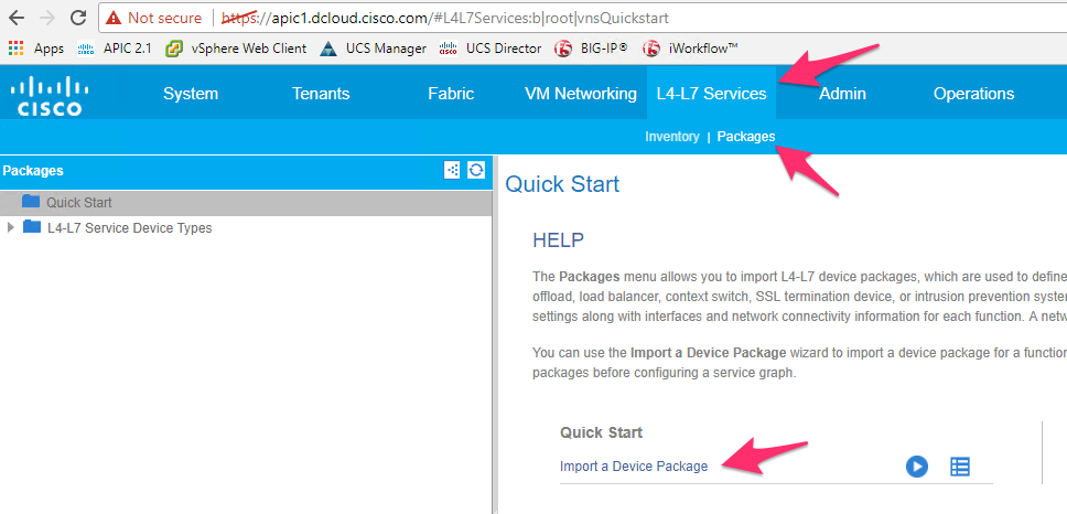
Click on Browse and then select the device package present on the desktop
Once uploaded, you can view the device package contents on the left-hand side of the pane
3.2.2.3. APIC
Let’s login to APIC and have a look at the configuration before we run the playbook
Let us now execute the playbooks on APIC.
Log back into the ‘Tools’ host, go to the
/rootdirectoryPlaybook
aci_tenant_setup.yaml– this playbook will perform the following tasks- Create a tenant
- Create a Private Context
- Create two bridge domains
- Create an application profiles
- Create two EPG (End Point Groups)
- Create a contract
To execute the playbook run command
ansible-playbook --step playbooks/aci_tenant_setup.yamlThe following gets created on APIC after playbook (
aci_tenant_setup.yaml) execution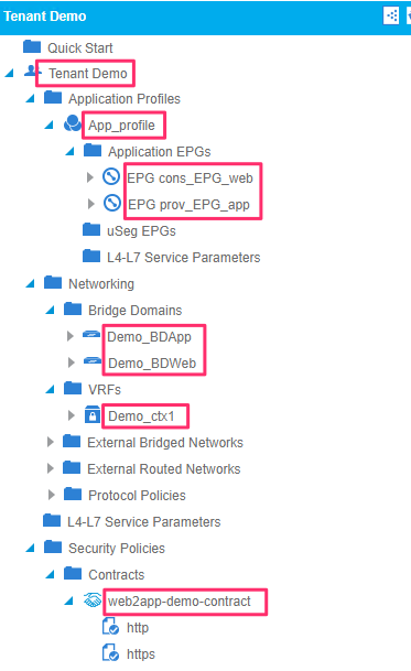
Playbook
logical_device_cluster.yaml– this playbook will perform the following tasks- Create a device manager type
- Create a device manager in tenant common
- Create a logical device cluster in tenant common
To execute the playbook run command
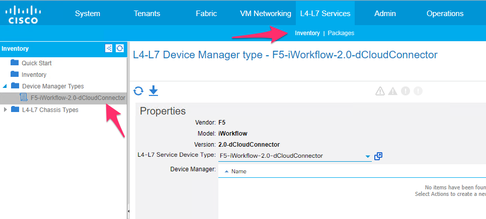
ansible-playbook --step playbooks/logical_device_cluster.yamlThe following gets created on APIC after playbook (
logical_sevice_cluster.yaml) executionDevice Manager Type under L4-L7 services->Inventory->Device Manager Types
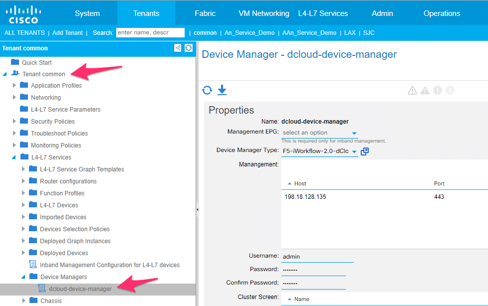
Device Manager under Tenant common ->L4-L7 services->Device Managers
Logical device cluster under tenant common -> L4-L7 Devices. Make sure before proceeding to the next step that your logical device cluster is in ‘Stable’ state
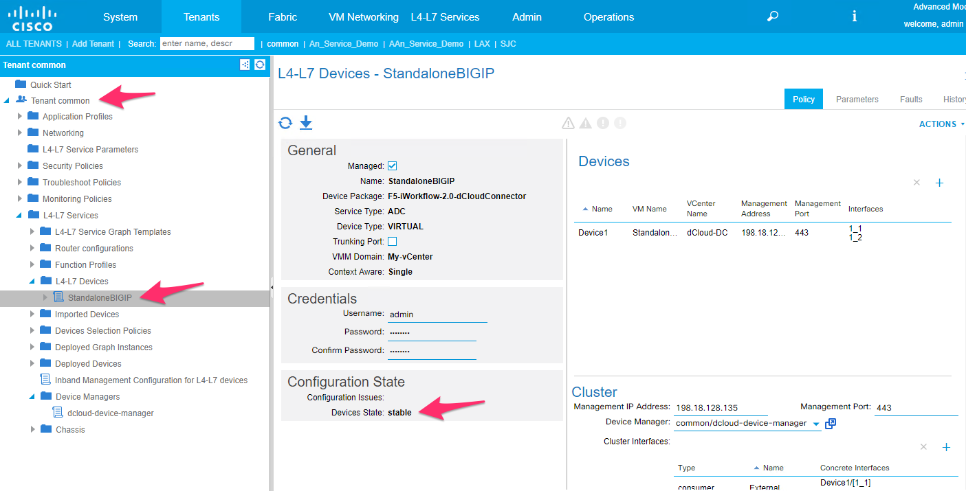
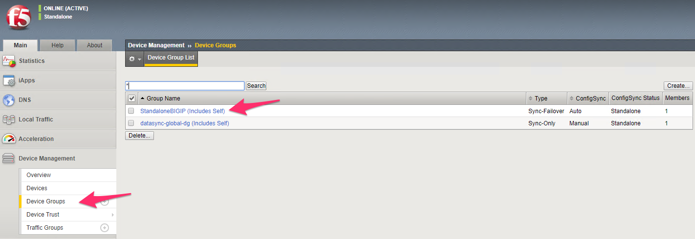
On the BIG-IP a device group will be created which has the same name as that of the logical device cluster
Playbook
service_insertion.yaml- this playbook will perform the following tasks- Export the logical device cluster from tenant common to user tenant
- Create a service graph template
- Assign L4-L7 BIG-IP parameters (VIP, Port etc.) to the graph
- Create a device selection policy
- Then attach the service graph template to the contract
To execute the playbook run command
ansible-playbook --step playbooks/service_insertion.yamlThe following gets created on APIC after playbook (
service_insertion.yaml) execution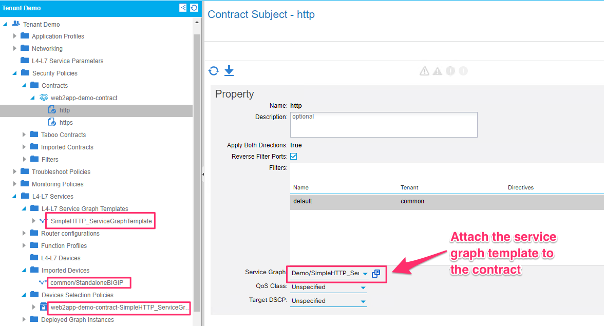
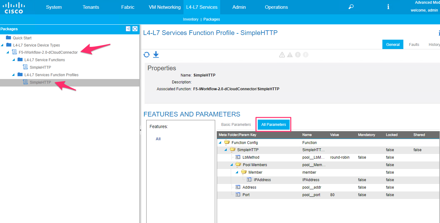
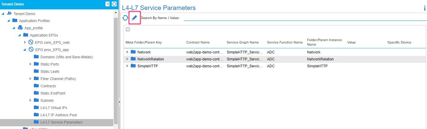
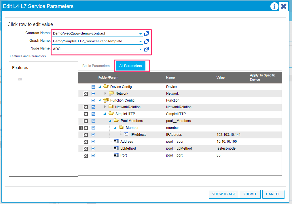
You can view the BIG-IP parameters that get configured under provider EPG. Click on the pencil edit button, select the appropriate graph/contract and node. Click on the ‘all parameters’ tab to view all the details
3.2.2.4. Verify
Verify successful deployment of network and application parameters on the APIC, iWorkflow, BIG-IP
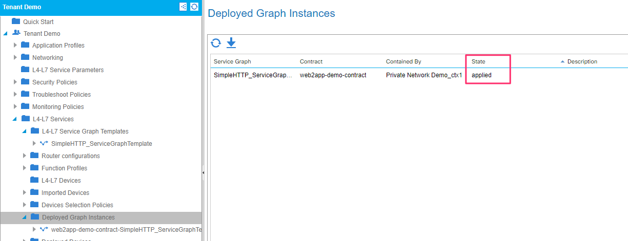
On the APIC make sure the graph is deployed and the state is ‘applied’
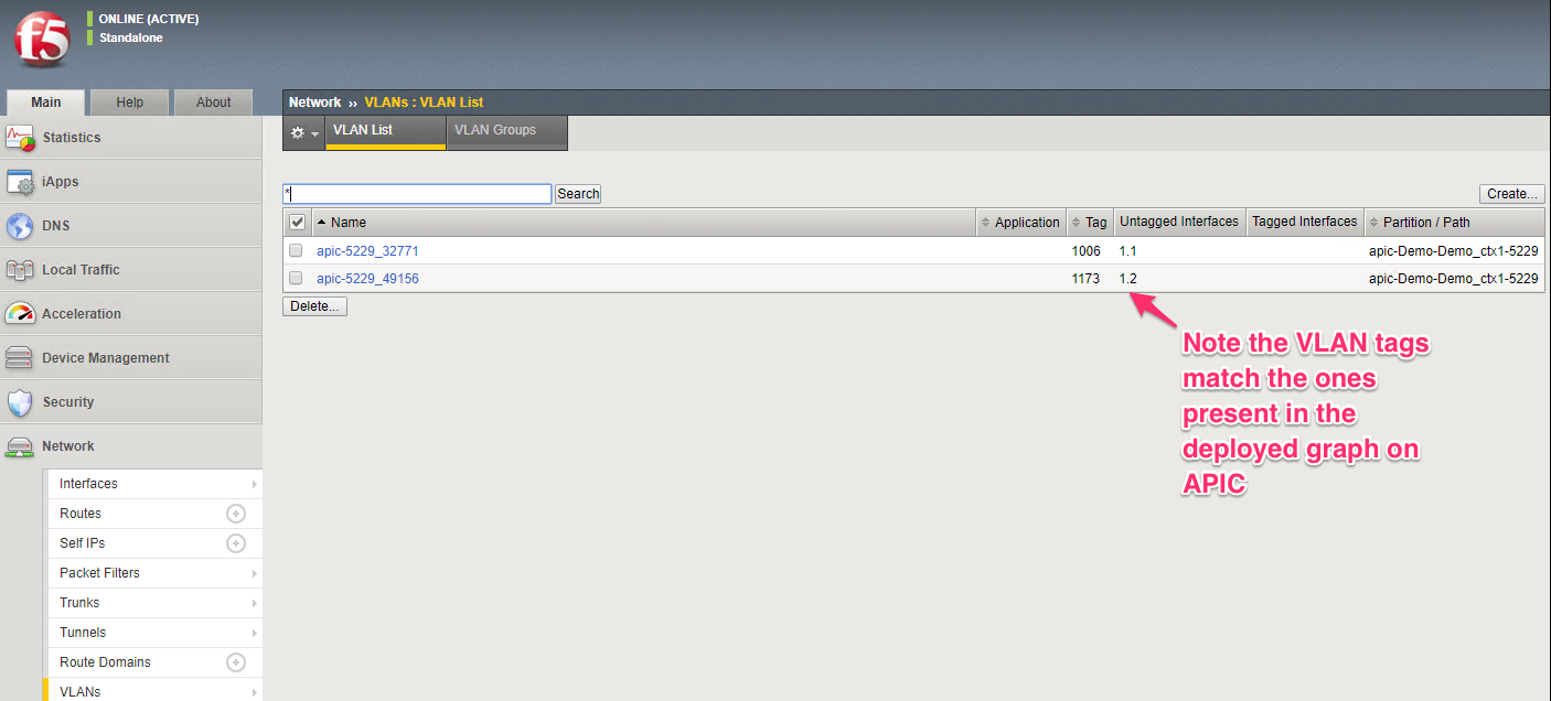
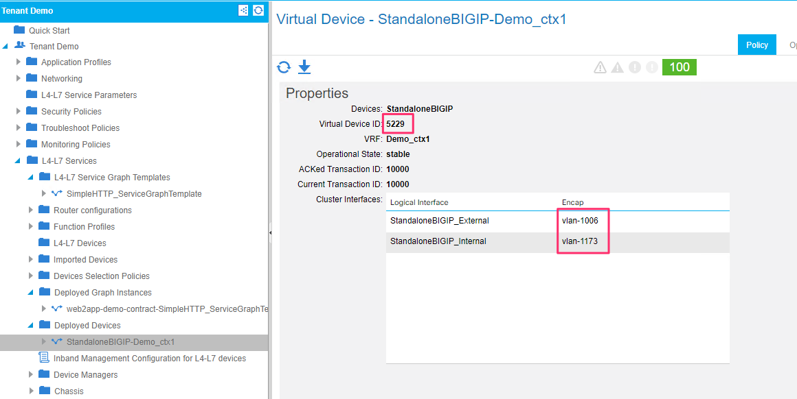
View the deployed devices tab and take node of the Virtual device ID. This will be the identified on the BIG-IP with which you can associate the partition created on the BIG-IP to the graph deployed on the APIC. Also keep note of the VLAN tags
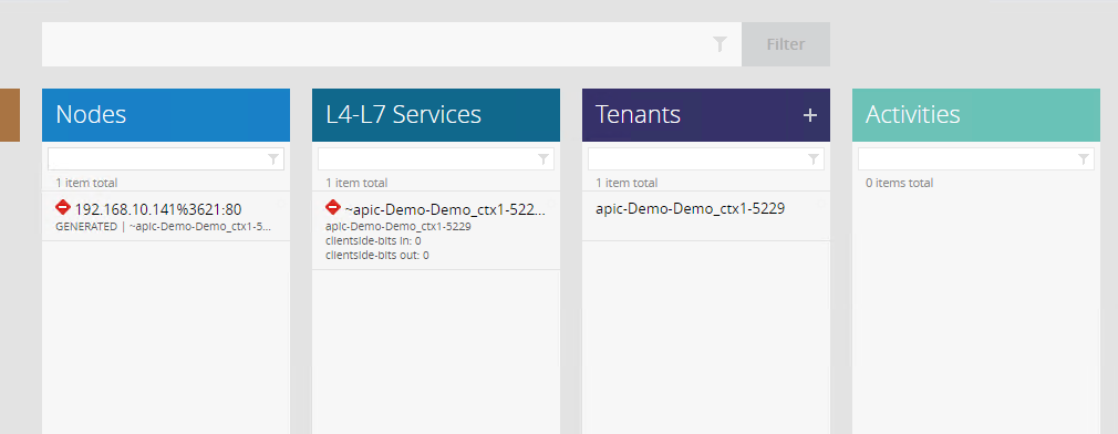
On the iWorkflow, make sure there is a
- Tenant created which will map to a BIG-IP partition
- A L4-L7 service which will map to the virtual server configured on the BIG-IP
- Nodes are created which map to the node members created on the BIG-IP
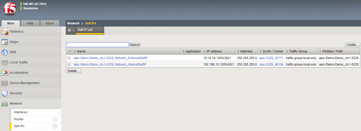
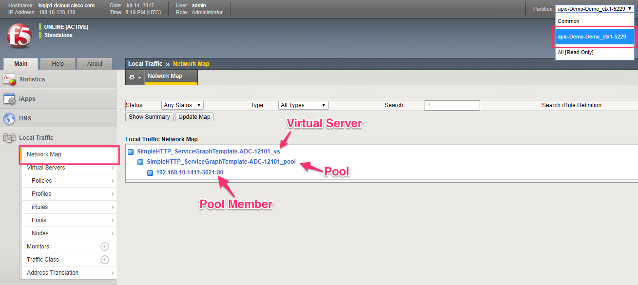
On the BIG-IP make sure a partition is created (note the partition is referencing the Virtual ID generated by APIC).
Click on ‘Network Map’ to get a unified view of the objects deployed on the BIG-IP. To see individual objects, click on the appropriate tab from the left hand pane
To view network related parameters, click on the ‘Network’ tab and then view the Self IP’s and the VLAN information. The Self IP information is user driver (part of the service graph). The VLAN information is dynamically generated by APIC which is configured on the BIG-IP