2.2. Deploy Service Graph using F5 iApps in Cisco ACI with F5 iWorkflow
2.2.1. Overview
Cisco Application Centric Infrastructure (ACI) technology provides the capability to insert Layer 4 through Layer 7 (L4-L7) functions using an approach called a service graph. One of Cisco ACI’s changes to the operation model with the service graph function is that a configuration now includes not only the network connectivity consisting of VLANs, IP addresses, etc., but also the configuration of access control lists, load-balancing rules, etc., on service appliances, such as the firewalls and load balancers. This approach differs from the traditional operation model of service insertion. Prior to Cisco ACI, the fabric configuration would have consisted only of connectivity for firewalls and load balancers. With Cisco ACI, the service graph configuration includes the ability to push configuration of firewalls and load balancers from ACI.
2.2.2. APIC GUI Layout
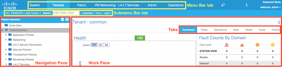
The top of the GUI screen is the Menu bar tab, the middle of the GUI is the Submenu bar tab, the bottom left of the GUI screen is the Navigation Pane, and the middle-right of the GUI is the Work Pane.
2.2.3. F5 iWorkflow and Cisco ACI Lab
The goal of this lab is to demonstrate a WEB application deployment that has L4-L7 ADC requirements in ACI environment. Using F5 iWorkflow service catalog model, the WEB application ADC requirements are defined in iWorkflow service catalog template using F5 iApps technology. Thru F5 dynamic device package, this service catalog is imported into ACI. In Cisco ACI, when deploy application WEB, administrator can now pick WEB template to apply ADC functionality to application WEB.
To achieve this scenario, you will configure ACI L4-L7 service insertion in managed mode with device manager using F5 BIG-IP VE Virtual ADC and F5 iWorkflow orchestration + automation platform using User Interface.
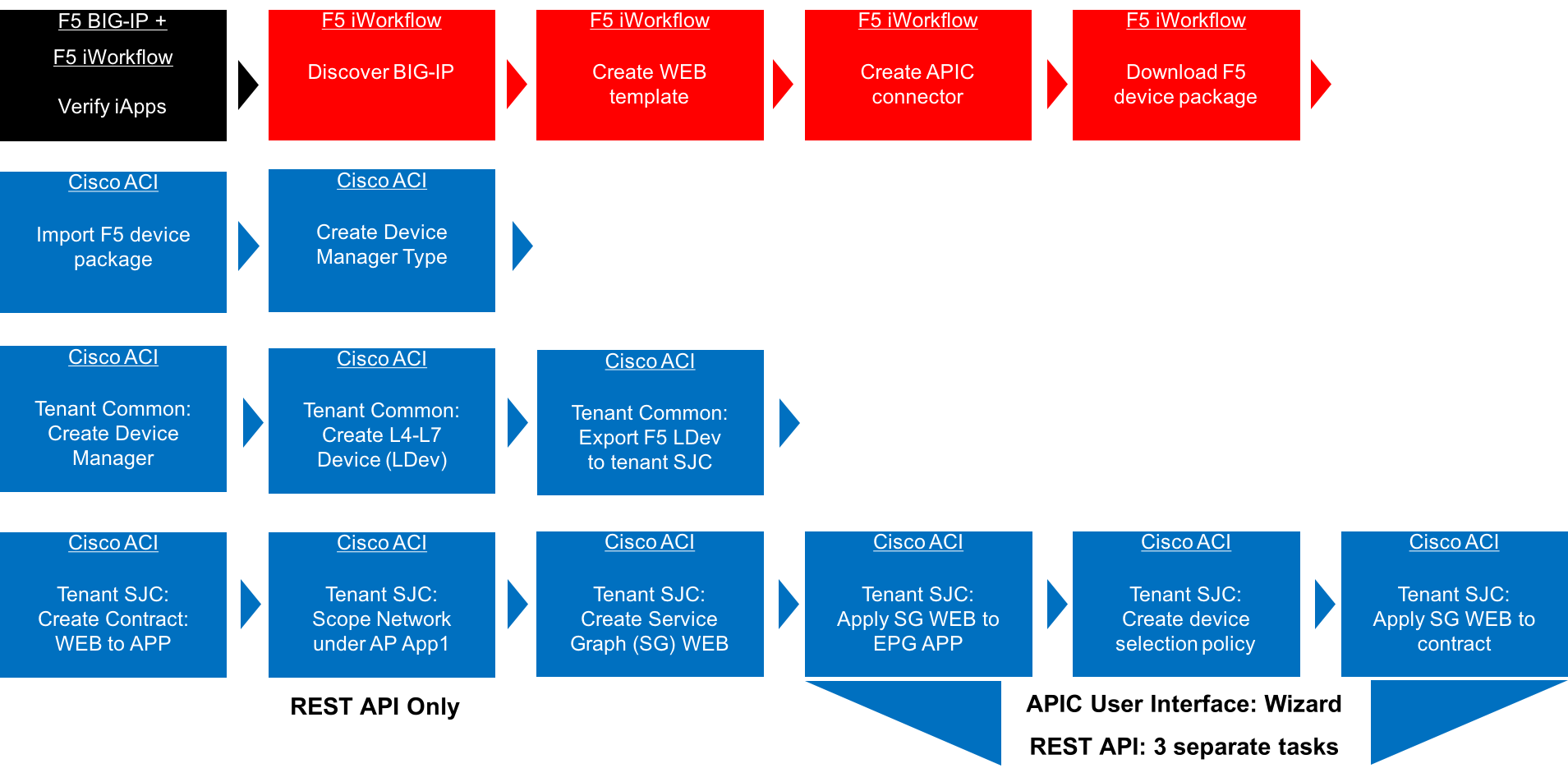
2.2.4. F5 iWorkflow and Cisco ACI Lab Flow Chart
2.2.5. BIG-IP – Verify the F5 BIG-IP iApps
F5 iApps is a user-customized framework for deploying application, providing a flexible way to automate tasks and templatize F5 virtual server configurations.
The iApps must be imported into F5 BIG-IP in order to allow F5 iWorkflow to create an application template based on this iApps. In this step, we will verify the iApps is already exist in F5 BIG-IP.
Log into the F5 BIG-IP with the following username and password from the web browser:
BIG-IP: https://198.18.128.130
Username: admin
Password: C1sco12345
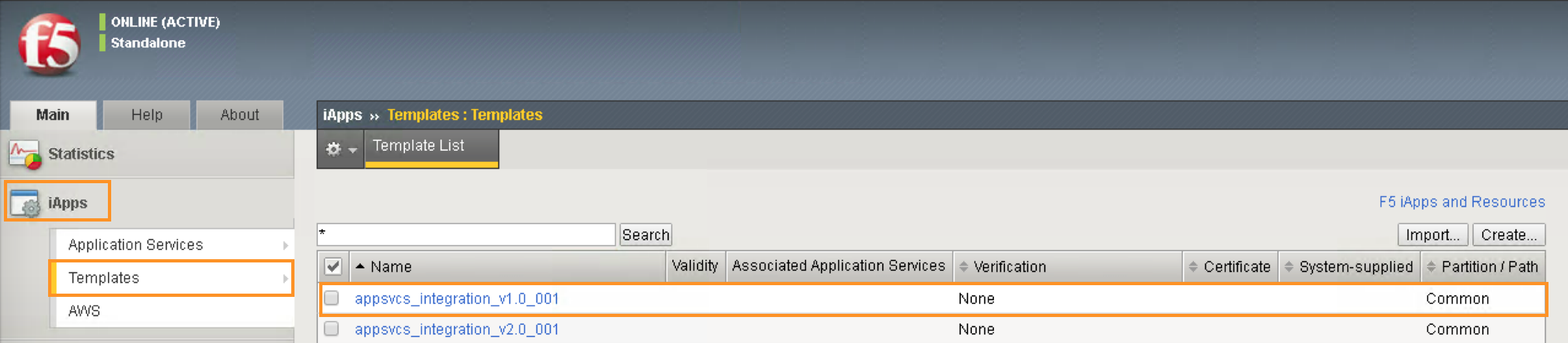
After you have logged into the F5 BIG-IP GUI. In the Navigation pane, click the iApps -> Templates. You should see the iApps template appsvcs_integration_v1.0_001 pre-loaded into the F5 BIG-IP:
Note
Up to iWorkflow release 2.0.2, iApps to be used by iWorkflow / APIC integration must be exist in BIG-IP in order for iWorkflow to be discovered. Beginning iWorkflow release 2.1.0, user import iApps into iWorkflow and iWorkflow will push the iApps to BIG-IP
2.2.6. iWorkflow – Set up the F5 iWorkflow Clouds and Services
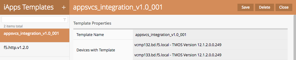
F5 iApps template is ALREADY added in iWorkflow:
F5 iWorkflow Clouds and Services allows administrator to create a cloud connector to Cisco APIC by generating a customized device package that contains the service catalog. It is also where administrator can manage service catalog life cycle.
In this step, we will configure F5 iWorkflow prior to Cisco ACI integration.
Log into the F5 iWorkflow 198.18.128.135 with the following username and
password from the web browser:
iWorkflow: https://198.18.128.135
Username: admin
Password: C1sco12345
After you have logged into the F5 iWorkflow GUI. Click on “Clouds and Services”, select “+” Devices
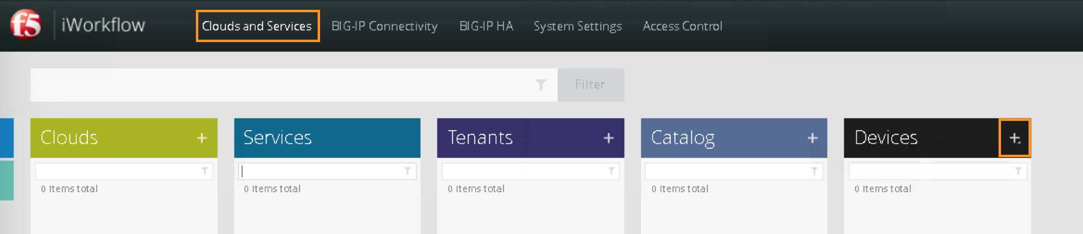
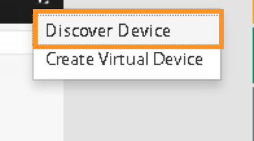
Register F5 BIG-IP by selecting “Discover Device”
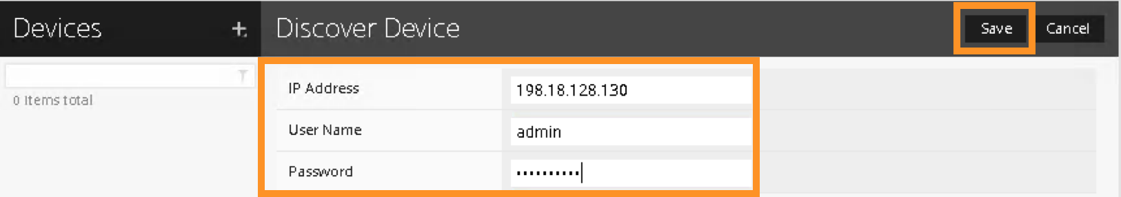
Register the F5 BIG-IP by using the BIG-IP’s IP address and credential as the following:
IP Address: 198.18.128.130
Username: admin
Password: C1sco12345
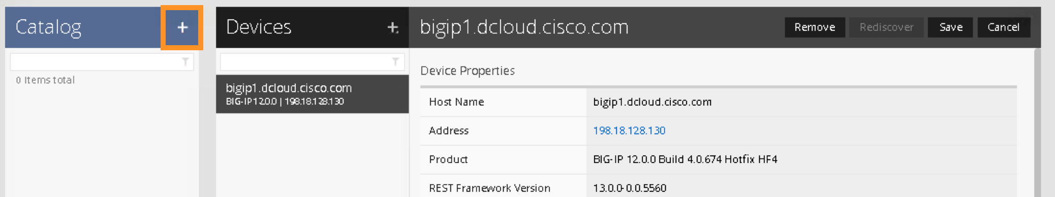
Click Save to register the BIG-IP device:
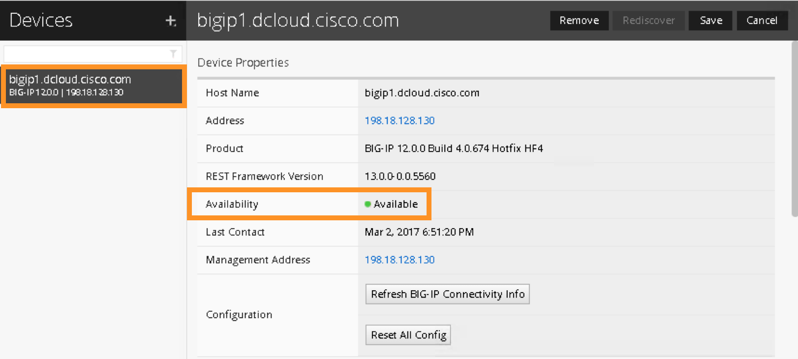
You can now double click the registered BIG-IP and verify its status. It should say “Available” when the BIG-IP is communicating with the iWorkflow:
2.2.7. iWorkflow – Create WEB application template in iWorkflow Catalog
After BIG-IP is successfully discovered by iWorkflow, the iApps reside on BIG-IP are now exposed to iWorkflow.
In this step, we will create a WEB application template based on iApps in iWorkflow Cloud Catalog. We can specify the WEB application F5 virtual server requirements here and build it into a template.
Move your mouse to the left or right side of the screen and the Cloud Catalog menu should appear, click “+” to add a template
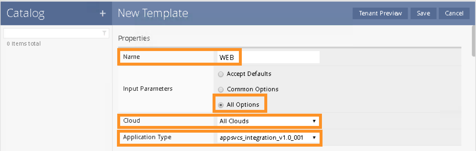
A New Template screen will appear. Enter and select the following in the New Template:
Name: WEB
Input Parameters: All Options
Cloud: All Clouds
Application Type: appsvcs_integration_v1.0_001
Note
Only field marked “Tenant Editable” will be visible in Cisco APIC
You can now edit all the available options that need to be included with this template.
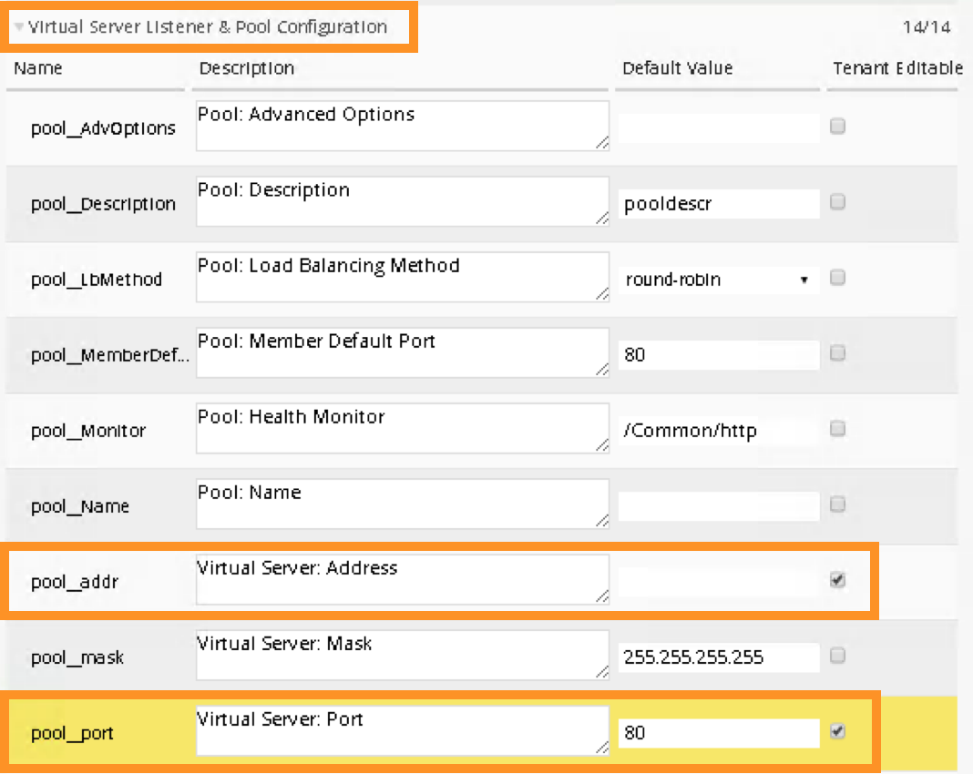
Expand the Virtual Server Listener & Pool Configuration by clicking the >. Scroll down and CHECK the following to make them Tenant Editable. What this does is allow the parameters expose to Cisco APIC thru F5 device package. Administrator has total control over what is exposed via a custom device package (this reduces the complexity). It is highly recommended to expose only what is needed to APIC:
pool__addr: this is the VIP
pool__port: this is the VIP listening port
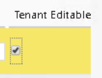
Note
By default, this iApp allows VIP as tenant editable field. When you check VIP listening port as tenant editable, iWorkflow will highlight it.
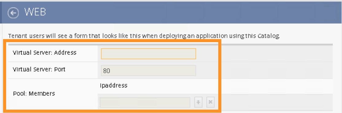
Click “Tenant Preview” to review the parameters will be visible in Cisco APIC:

You should only see 3 parameters:
Virtual Server: Address
Virtual Server: Port
Pool: Members
Click  to go back, then “Save”

Notice a new application template now under iWorkflow Cloud Catalog. The “Save” operation will also update the F5 iWorkflow Cloud APIC device package with the updated service catalog.
This service catalog is ready to be consumed by Cisco APIC.

2.2.8. iWorkflow – Create F5 iWorkflow APIC device package
The next step is to create the iWorkflow Cloud APIC Connectors which will generate a custom device package that contains iWorkflow service catalog. The template we created in the previous step will appear in APIC as a service function.
Move your mouse to the left / right side of the screen to make the Clouds menu to appear.
To create a new Connectors, move the mouse to the Clouds menu and the + should appear.
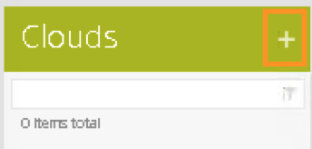
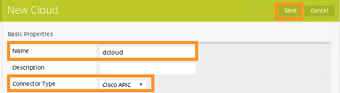
Click “+” to create a new Cloud Connector:
Name: dcloud
Connector Type: Cisco APIC
Click “Save” to finish
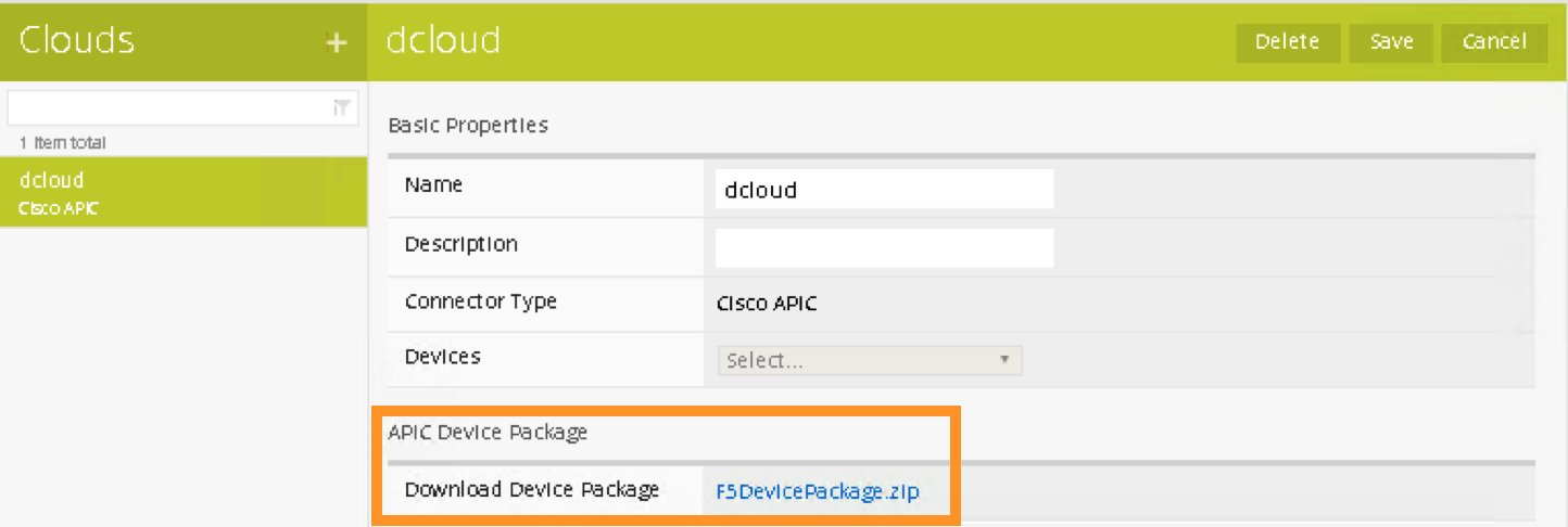
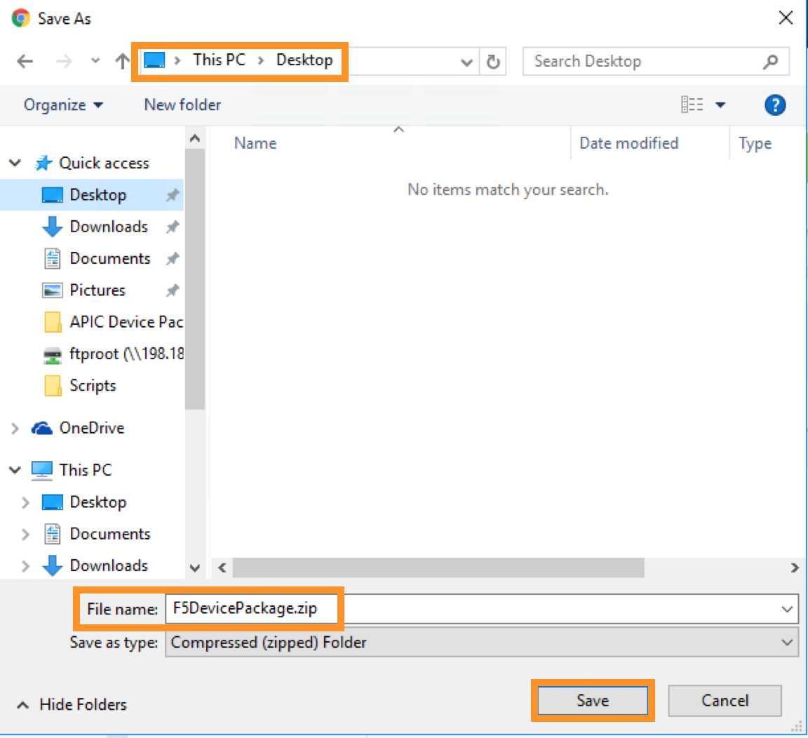
Double Click the dcloud connector, you can download this customized device package that contains iWorkflow Catalog to your desktop.
We now complete the configuration steps on iWorkflow necessary prior to F5 ACI integration.
2.2.9. APIC – Import the Custom Device Package
Starting here, you will use Cisco APIC to perform the workflow in deploying the WEB application, with the integration of F5 iWorkflow and BIG-IP, user can apply WEB application L4-L7 requirements within APIC policy model, reducing significant amount of operation complexity.
In this step, you will import the customized device package generated by F5 iWorkflow into Cisco APIC. This will allow the iWorkflow service catalog available in Cisco APIC. The device package serves as a conduit to facilitate communications between F5 iWorkflow and BIG-IP.
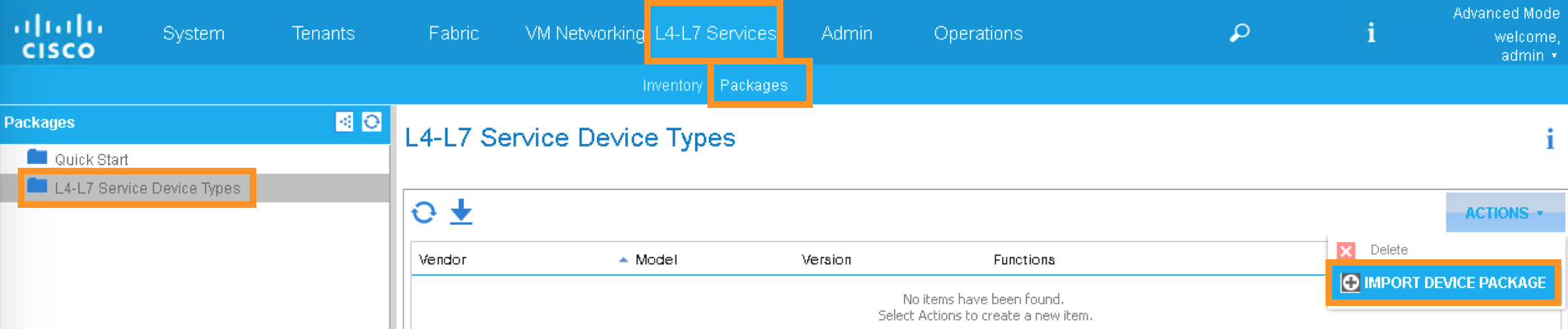
Switch to your APIC GUI and click the following to import the device package:
L4-L7 Services -> Packages -> L4-L7 Service Device Type
Click the ACTIONS button at the Work pane and choose IMPORT DEVICE PACKAGE
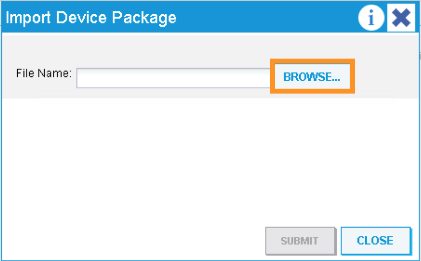
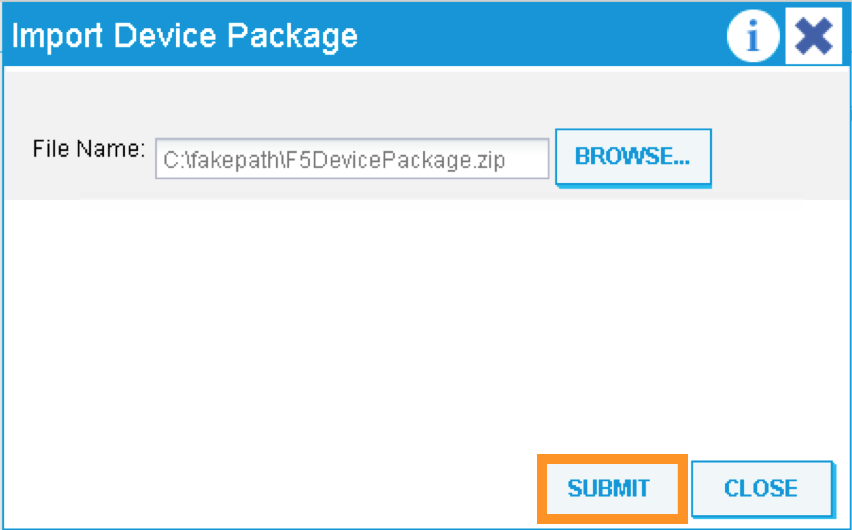
A new pop-up should appear to allow you to choose the device package to be installed, click “Browse”:
Go to Desktop and select F5DevicePackage.zip
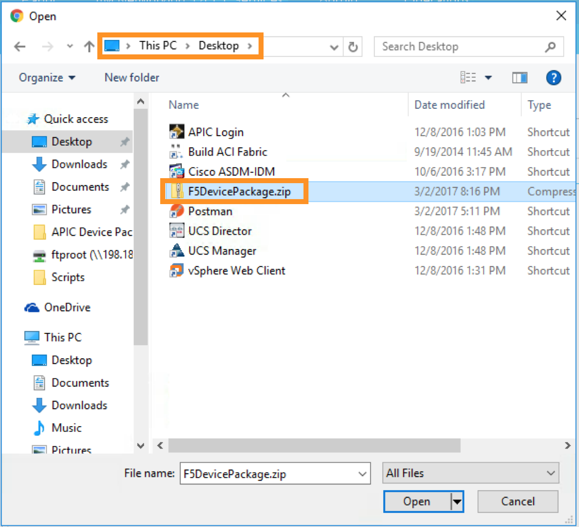
Click “Submit”
Now F5 device package is imported into APIC
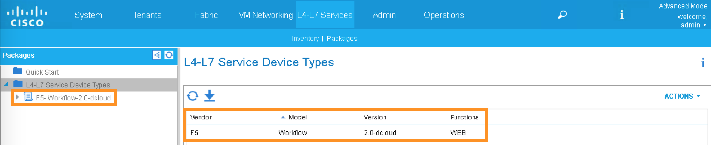
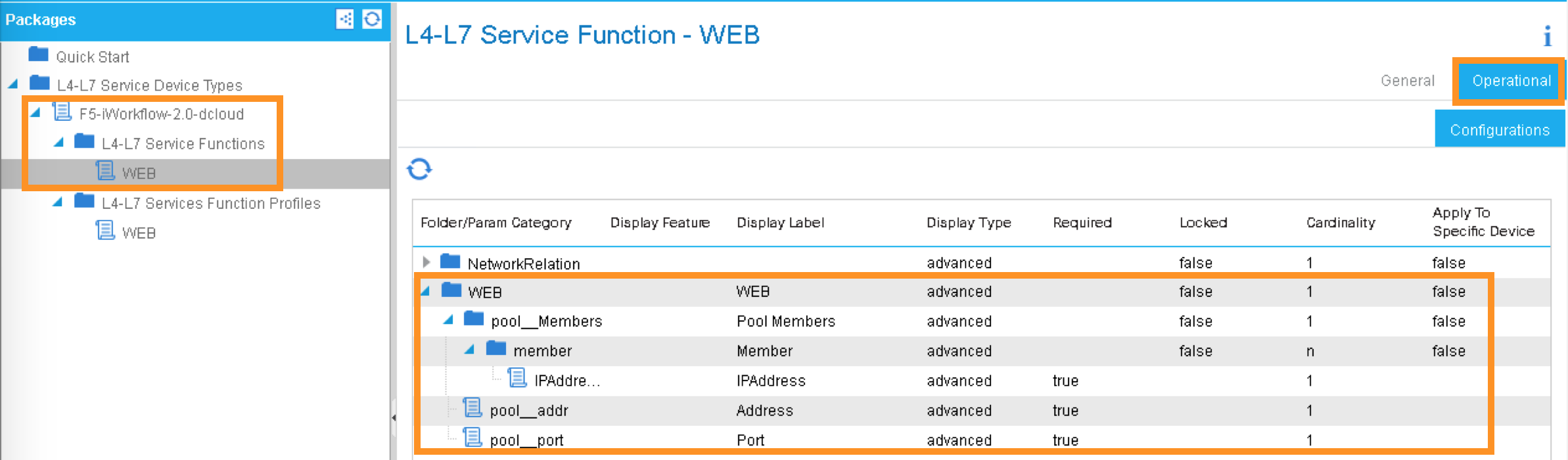
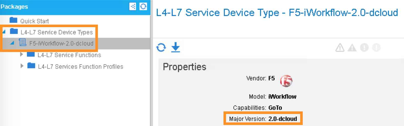
Expand the Device Package, notice Service Function “WEB” is equivalent to iWorkflow Catalog template “WEB”. Under Operational, parameters visible in APIC are the “Tenant Editable” parameters in iWorflow:
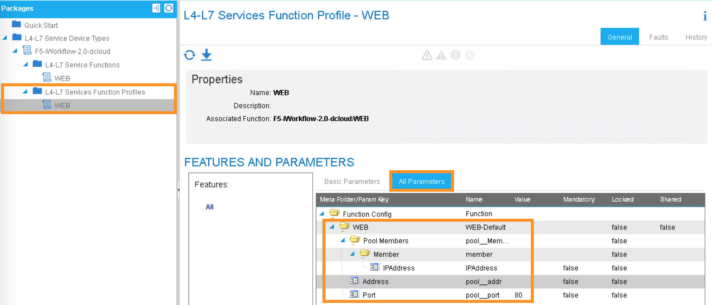
Under Function Profiles, you can see if there is any default value assigned to the parameters:
2.2.10. APIC – Create APIC L4-L7 Device Manager under L4-L7 Services
In order to integrate F5 iWorkflow cluster into Cisco APIC L4-L7 devices, we use Cisco APIC device manager feature to define and specify F5 iWorkflow.
From APIC perspective, F5 iWorkflow is a “device manager” managing the F5 BIG-IP ADC (both physical and virtual form factors).
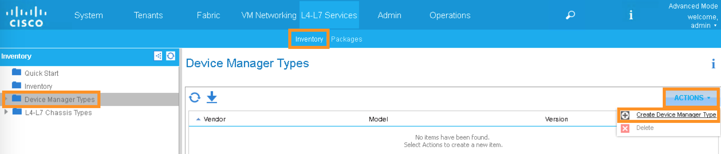
We will first define the device manager type. In the APIC GUI, click the following to configure the Device Manager Type:
L4-L7 Services -> Inventory -> Device Manager Type
Click the ACTIONS button at the Work pane and choose Create Device Manager Type
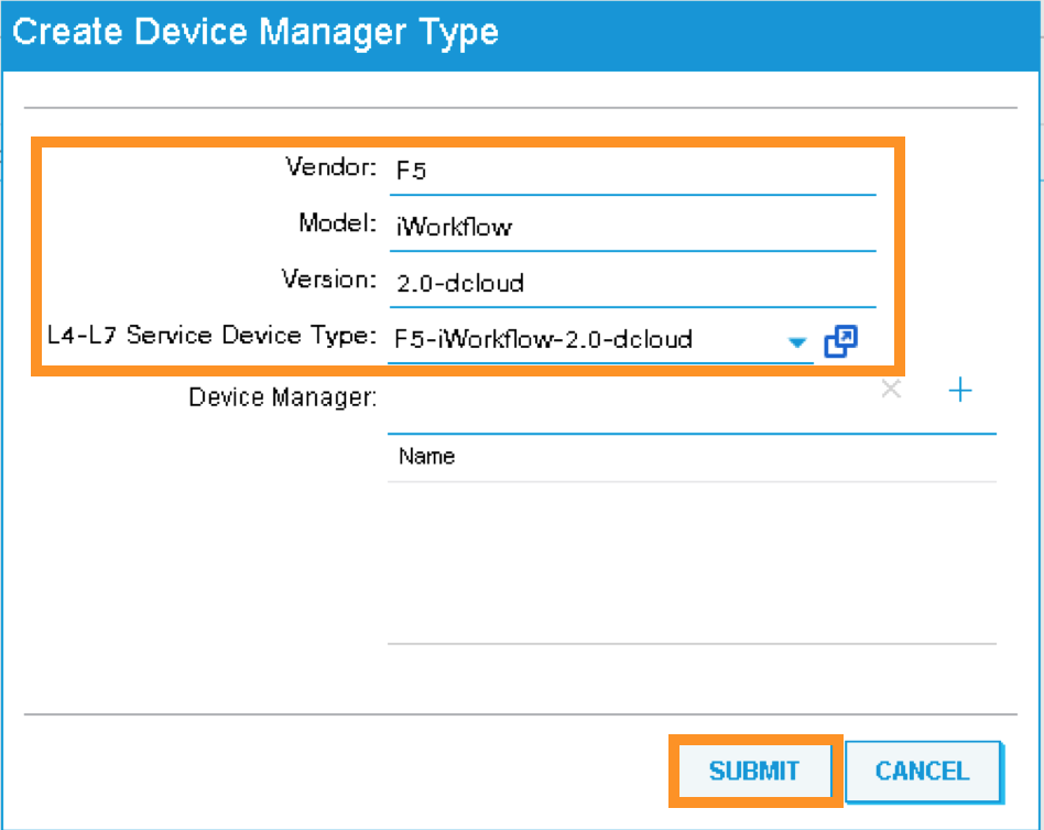
A new pop-up should appear to allow you to enter the device manager information. Enter the following information:
Vendor: F5
Model: iWorkflow
Version: 2.0-dcloud
L4-L7 Service Device Type: F5-iWorkflow-2.0-dcloud
Device Manager: Leave this field empty
Note
It is extremely import to match the Version number with the major version of the device package
Click SUBMIT to accept the configuration.
The Device Manager Type is now configured and we can now associate this device manager type with a device manager.
2.2.11. APIC – Create Device Manager under Tenant Common
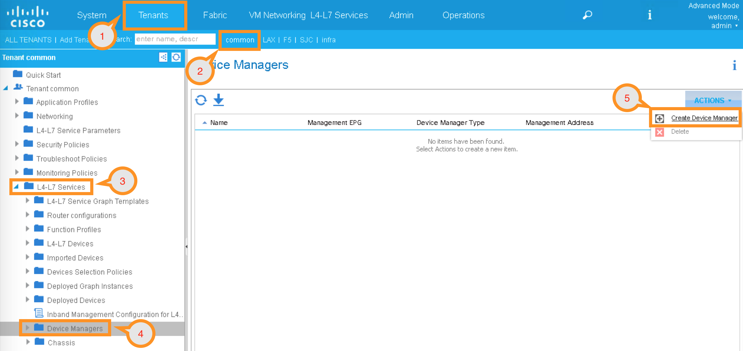
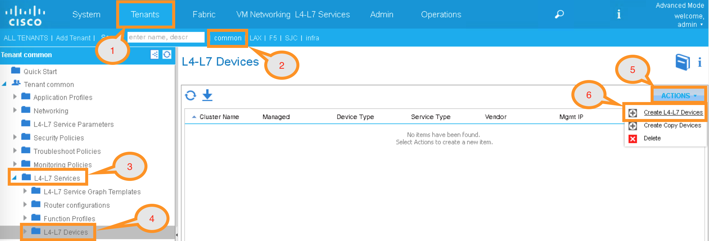
To create a device manager, navigate to your tenant common to create a new L4-L7 Device Manager by clicking the following:
Tenants Common -> L4-L7 Services -> Device Managers
In the Work pane, click: ACTIONS -> Create Device Manager
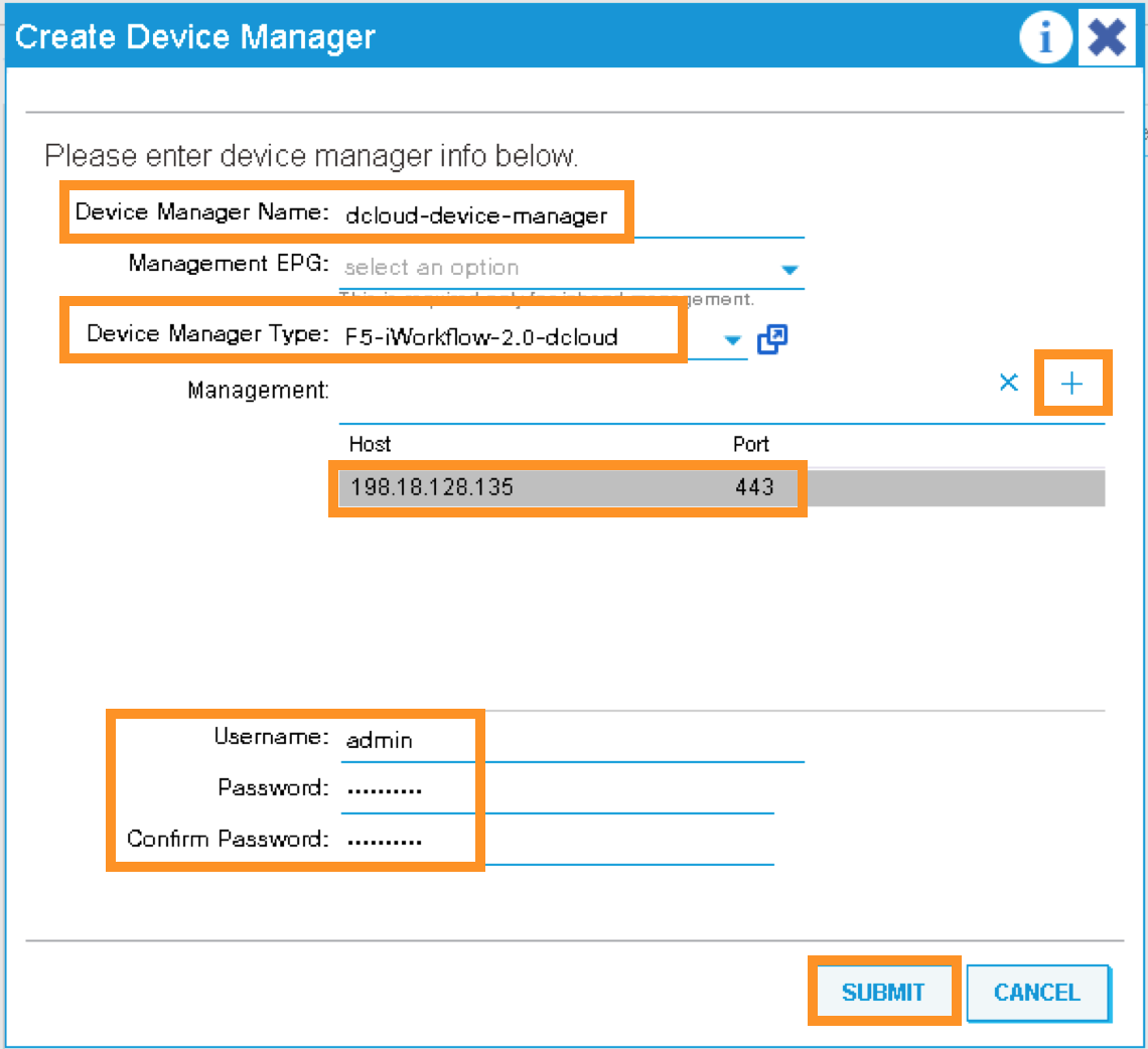
A new pop-up should appear to allow you to Create Device Manager in your tenant. You will specify F5 iWorkflow management IP here and associate it with the device manager type created in the previous step. Enter the following information:
Device Manager Name: dcloud-device-manager
Management EPG: Leave this field empty since we use OOB to communicate
Device Manager Type: F5-iWorkflow-2.0-dcloud
Click the + to enter the iWorkflow management IP for device manager Management connectivity:
Host: 198.18.128.135
Port: 443
Click UPDATE to accept.
Enter the Device Manager’s login credential:
Username: admin
Password: C1sco12345
Confirm Password: C1sco12345
Click SUBMIT to accept the configuration.
This complete the steps to create APIC L4-L7 device manager. We will use this device manager in the next step when creating APIC L4-L7 device.
2.2.12. APIC – Create the L4-L7 Device
In this step, we will create an APIC L4-L7 device, this is the logical construct that contains F5 BIG-IP and iWorkflow information. You will see in the later steps on how to build an APIC service graph using this L4-L7 device.
Navigate to your tenant to create a new L4-L7 Device by clicking the following:
Tenants Common -> L4-L7 Services -> L4-L7 Devices
In the Work pane, click:
ACTIONS -> Create L4-L7 Devices
A new window should appear for you to create the L4-L7 Devices.

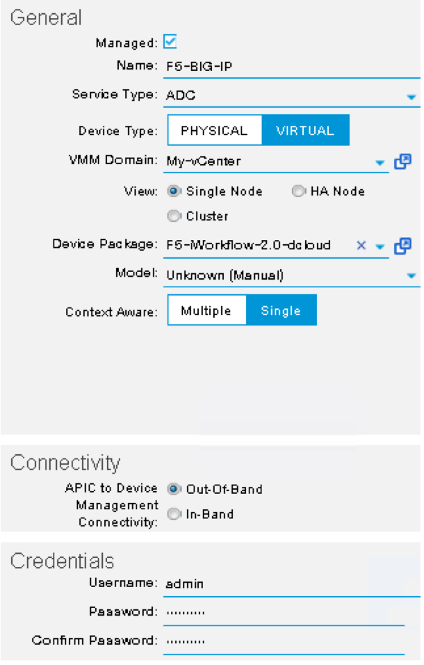
In the Create L4-L7 Devices window, enter the following:
Managed: CHECK
Name: F5-BIG-IP
Service Type: ADC
Device Type: Virtual
VMM Domain, click the down arrow to select: My-vCenter
Mode: Single Node
Device Package: F5-iWorkflow-2.0–dcloud
Model: Unknown (Manual)
Context Aware: Single
APIC to Device Management Connectivity: Out-Of-Band
Username: admin
Password: C1sco12345
Confirm Password: C1sco12345
After completion, it should look like:
What did I configure?
Managed: this means this L4-L7 device will be managed by Cisco APIC to be used in L4-L7 service insertion
Name: User defined name of the L4-L7 device
Service Type: Firewall or ADC, F5 BIG-IP is considered an ADC device
Device Type: Physical or Virtual, we use BIG-IP Virtual Edition in this lab
VMM Domain: If device type is virtual, select the VMM domain for this L4-L7 device, the VMM domain contains BIG-IP VE virtual machine
Mode: Single or HA, in this lab, only one BIG-IP VE, so select Single Node
Device Package: Drop down menu, pick the device package dcloud
Model: Choose Unknown(Manual) giving you flexibility to enter any F5 BIG-IP interface convention
Context Aware: Single Context device can be used by only 1 tenant; where Multi Context device can be shared among multiple tenants. In the case of virtual, we will select single context
APIC to Device Management Connectivity: All management connections are out-of-band in this lab Credentials: F5 BIG-IP admin credentials
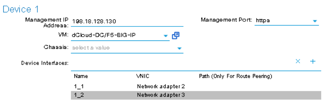
On the right-hand side of the wizard, in the Device 1, enter the following:
Management IP Address: 198.18.128.130
VM: Click the down arrow and select dcloud-DC/F5-BIG-IP
Management Port: https
Click the + to add a Device Interface:
Name: 1_1
VNIC: Network adapter 2
Click UPDATE to accept the Device Interface configuration.
Click the + to add 2nd Device Interface:
Name: 1_2
VNIC: Network adapter 3
Click UPDATE to accept the Device Interface configuration.
What did I configure?
Under Device 1, enter the BIG-IP VE management IP and management port of https (443)
Since this is a BIG-IP VE cluster, the VM field is visible and based on the VMM domain specified earlier, pick the VM for this L4-L7 device.
Device Interfaces: specify the BIG-IP VE interface to be used in data plane. We are configuring physical 2-arm in this lab, two BIG-IP interfaces are specified in this cluster. Notice the interface naming is 1_1, which is equivalent to interface 1.1 of BIG-IP. “_” is used instead of “.” is because APIC does not allow “.” as parameter value.
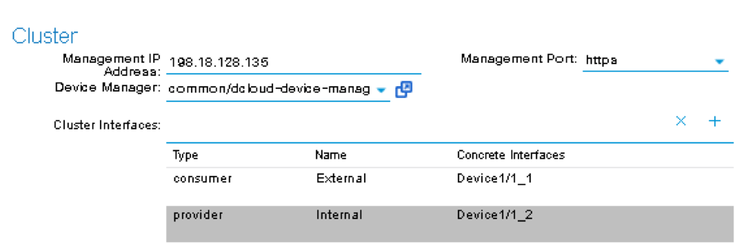
Next part of the configuration is L4-L7 device cluster information.
By default, APIC will populate Device 1’s management IP as the Cluster Management IP. In this lab, since we are going to use the iWorkflow to manage BIG-IP, the Cluster IP will be changed to the iWorkflow’s IP. The device will eventually ignore this setting and it will use the Device Manager information configured earlier to establish communication.
Management IP Address: 198.18.128.135
Management Port: https
Device Manager: common/dcloud-device-manager
Click the + to add the 1st Logical Interface:
Type: consumer
Name: External
Concrete Interface: Device1/1_1
Click UPDATE to accept the consumer interface configuration.
Click the + to add the 2nd Logical Interface:
Type: provider
Name: Internal
Concrete Interface: Device1/1_2
Click UPDATE to accept the consumer interface configuration.
Make sure all L4-L7 Devices parameters are entered correctly, click “NEXT”

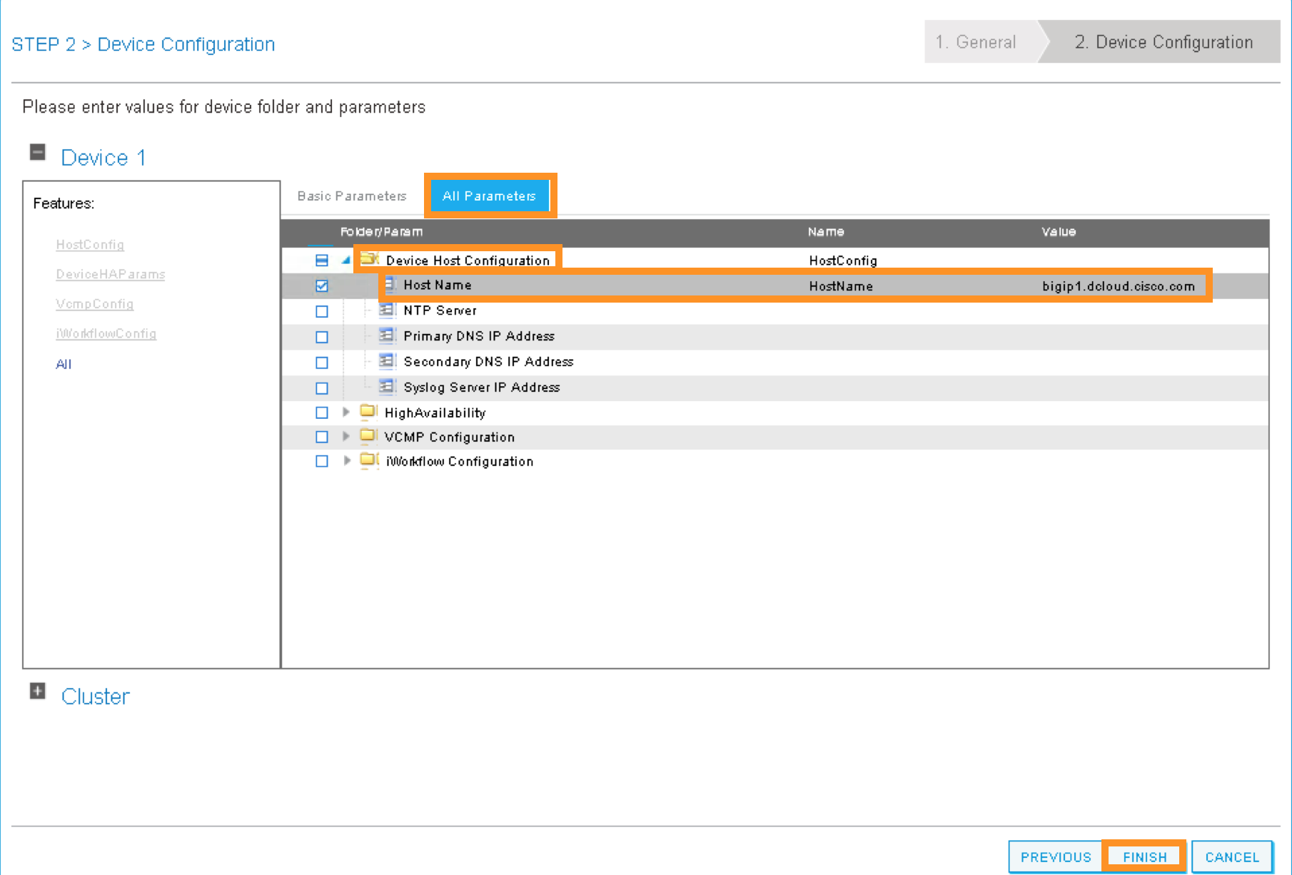
STEP2, Device Configuration. We would like to set up some basic information on the BIG-IP by choosing the All Parameters tab.
Click > to expand the field Device Host Configuration and enter the following parameters and click UPDATE to save the change:
Host Name: bigip1.dcloud.cisco.com
Click “FINISH”
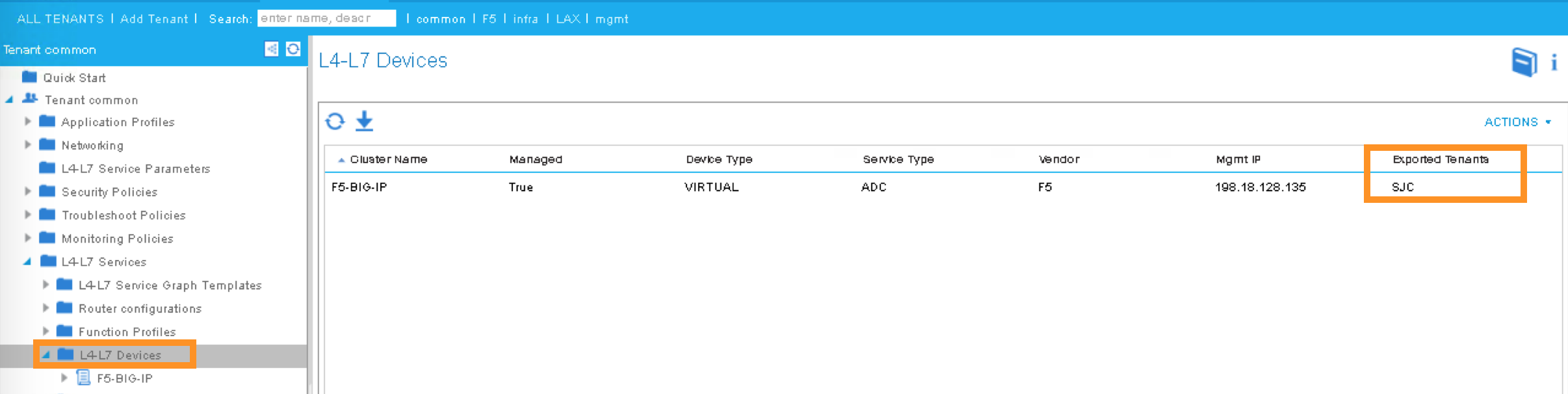
Navigate to the newly created L4-L7 Device to verify its Configuration State is stable:
Tenants common ->L4-L7 Services -> L4-L7 Devices -> F5-BIG-IP
In the Work pane, ensure the Configuration State is stable, if the device is not stable, click the Faults tab and ensure no faults or all the faults are in clearing state.
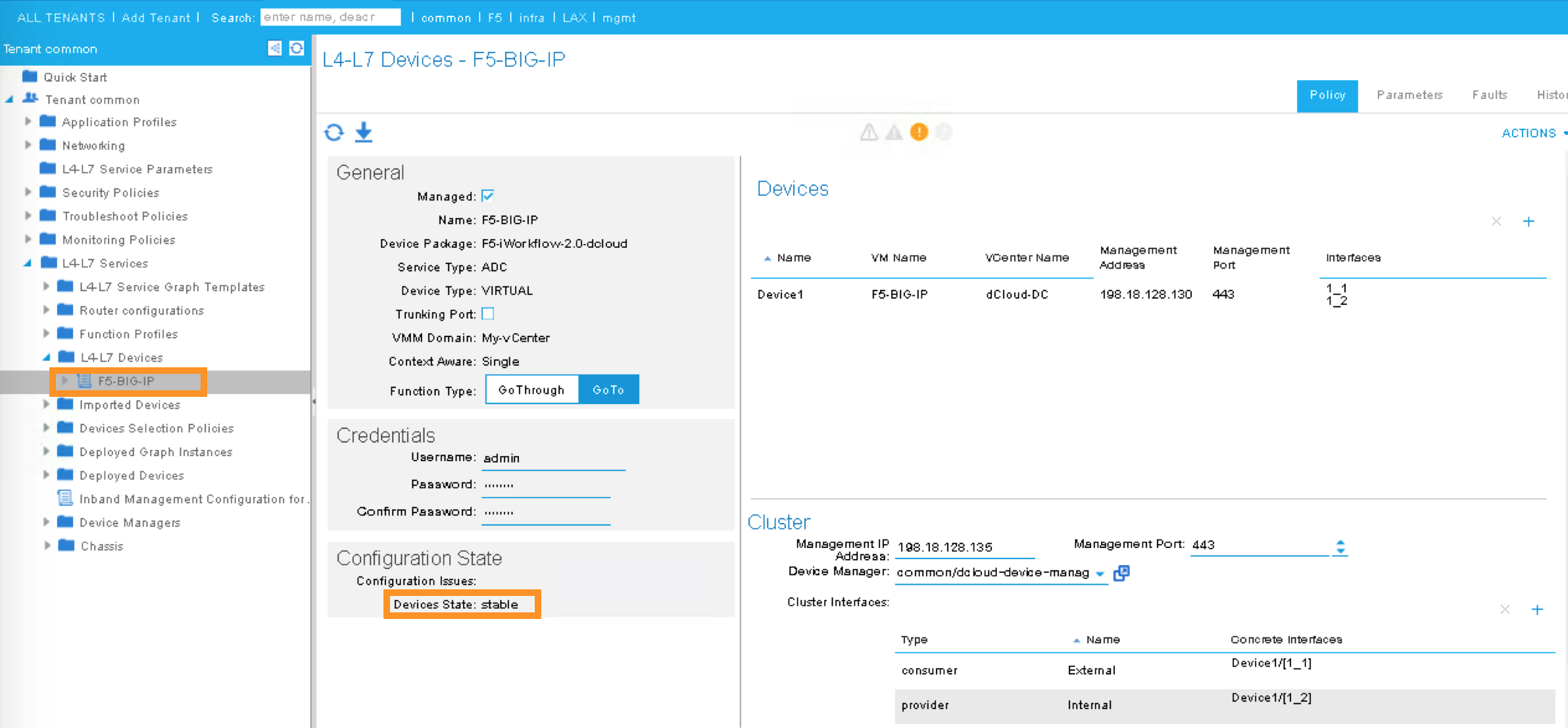
We now complete the configuration of the ACI L4-L7 device, and we will use this device when creating L4-L7 Service Graph Template in the next step.
2.2.13. APIC – Export L4-L7 Device to Tenant
Export F5-BIG-IP L4-L7 device as a resource to another tenant where application profile is configured.
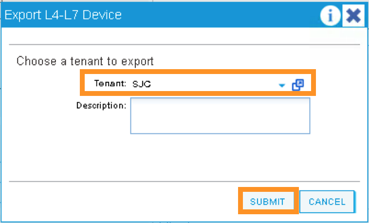
Right click on F5-BIG-IP, and select “Export L4-L7 Device”
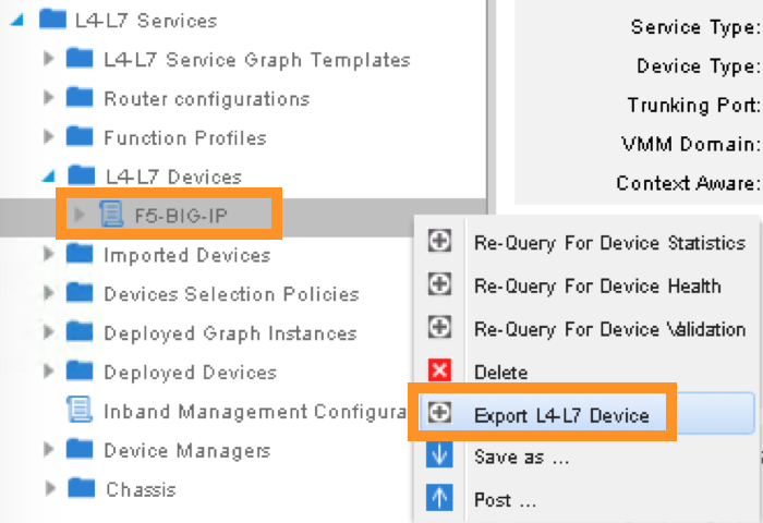
Drop down and select tenant “SJC”, the “SUBMIT”
2.2.14. APIC – Create L4-L7 Service Graph Templates
An APIC L4-L7 Service Graph Template is an abstract object allowing L4-L7 configuration build into ACI policy model. In this step, you will create a service graph template and add L4-L7 device you created in the previous step, then select the WEB service function for this graph.
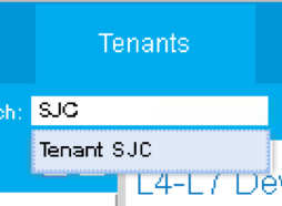
Go to Tenant SJC by typing “SJC” in the Tenant search box
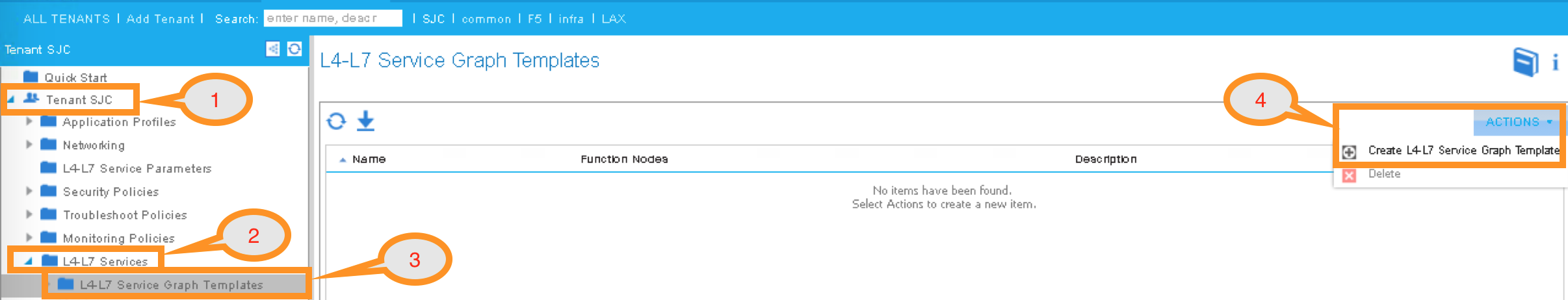
To create a new Service Graph Template, click the following in the navigation pane:
Tenants SJC -> L4-L7 Services -> L4-L7 Service Graph Template
In the Work pane:
ACTIONS -> Create L4-L7 Service Graph Template
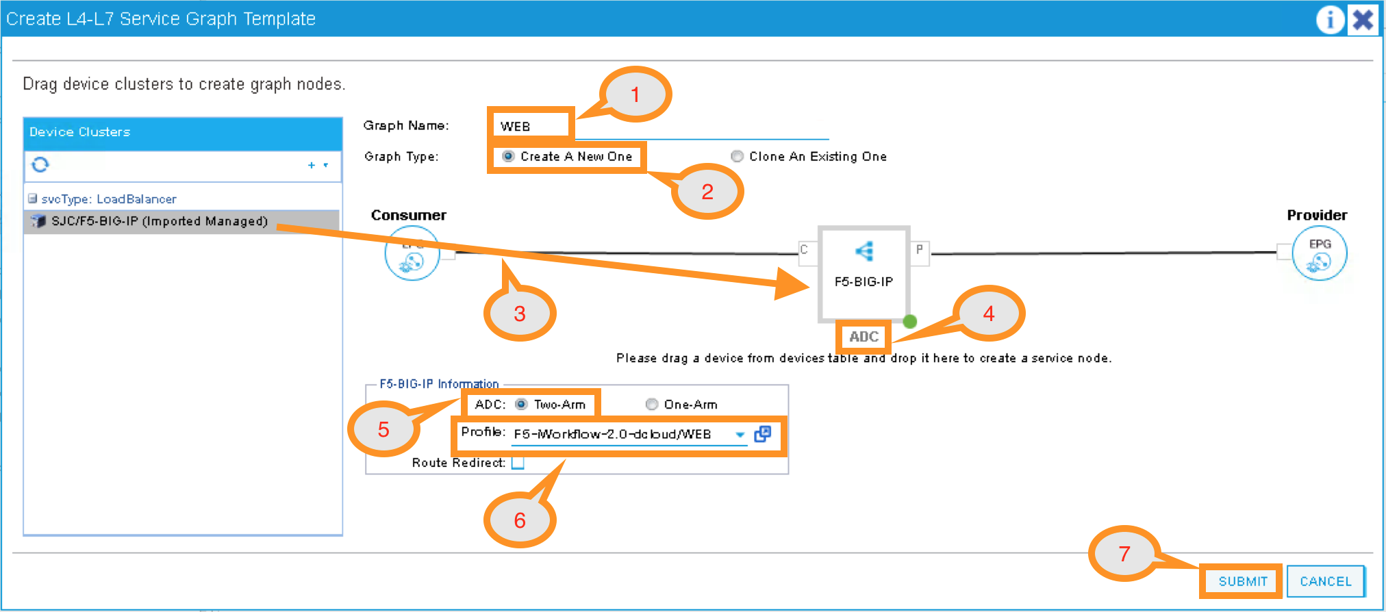
In the new window, enter the following:
Graph Name: WEB
Graph Type: Create a New One (should be the default)
Now, drag the Device Clusters to the right side of the window into the graph. You should be able to place the Node “SJC/F5-BIG-IP (Imported Managed)” between the Consumer EPG and the Provider EPG.
When this graph template is deployed, the traffic will be redirected to the F5 BIG-IP of this device cluster automatically by Cisco ACI.
Double click the word N1 under the Node to change the name to ADC.
Under F5-BIG-IP Information, click the Two-Arm option for this graph.
Select the Profile: F5-iWorkflow-2.0–dcloud/WEB <- this coming from the F5 device package
This is WEB application template that we created earlier.
Click “SUBMIT”
2.2.15. APIC – Deploy the Service Graph (EPG and Contract selection)
The new ADC L4-L7 Service Graph Template is now created and we are ready to deploy the BIG-IP with the pre-created web and app EPG.
In this step, we are deploying WEB graph, connecting between the web tier and the app tier. Inside contract between the web and app EPG, we will assign the service graph template created in the previous step, this will provide F5 BIG-IP ADC functionality to APP tier.
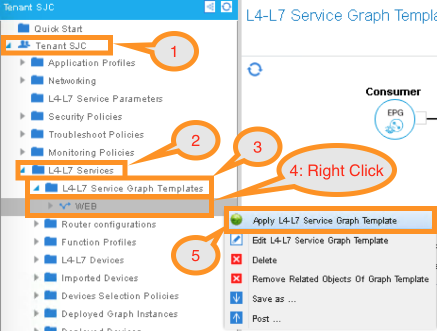
To deploy the service graph, click the following in the Navigation pane of your tenant:
Tenants SJC -> L4-L7 Services -> L4-L7 Service Graph Template
Select the Service Graph Template you just created from the Work pane. Right click and choose the option to
Apply L4-L7 Service Graph Template
In the new window, you will have the ability to choose which EPGs the Service Graph will be inserted in between.
Select the following for the EPG information:
Consumer EPG / External Network: SJC/App1/epg-web
Provider EPG / External Network: SJC/App1/epg-app
Under Contract Information, use the option to create a new Contract:
Create a New Contract: SELECTED
Contract Name: web2app-contract
No Filter (Allow All Traffic): CHECKED
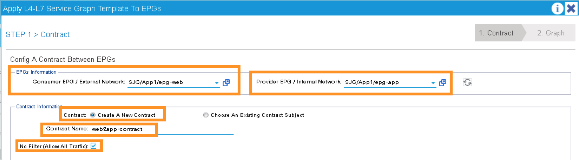
Click NEXT to continue to the next screen.
2.2.16. APIC – Deploy the Service Graph (Connectivity to Fabric)
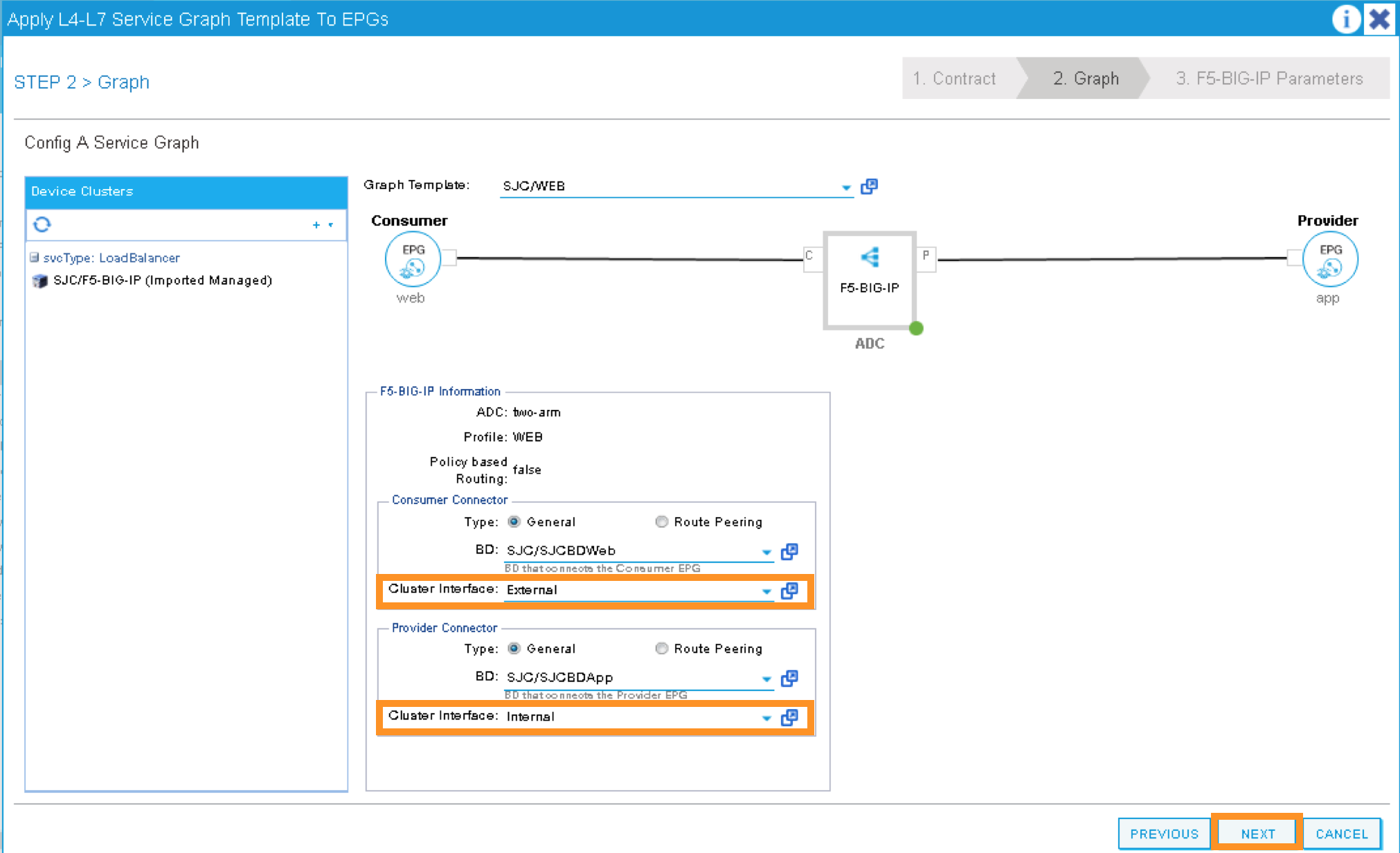
A new window to apply the service graph template will now appear. This window will show the Service Graph Template that you created earlier.
In addition to the Service Graph Template, there are some options that need to be selected to deploy the BIG-IP with a Service Graph. Under the SJC/WEB Information, you need to choose the appropriate connector information:
Under the Connector, choose the following:
Type: General
BD: SJC/SJCBDWeb
Cluster Interface: External
We use the External interface for the communication between the BIG-IP and the Web servers. The Web servers belong to Web EPG, which tied to the SJCBDWeb Bridge Domain.
Type: General
BD: SJC/SJCBDApp
Cluster Interface: internal
We use the Internal interface for the communication between the BIG-IP and the App servers. The App servers belong to App EPG, which tied to the SJCBDApp Bridge Domain.
Click NEXT to continue to the next screen.
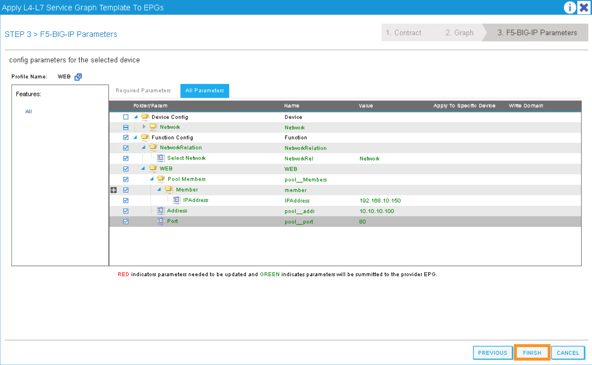
2.2.17. APIC – Deploy the Service Graph (BIG-IP Parameters)
A new window for the BIG-IP parameters will now appear. In this window, you will have the ability to modify the parameters to be deployed to the BIG-IP. Let us modify some parameters to push the Service Graph into the BIG-IP.
Under Feature, it should be selected All. Parameters should be All Parameters.
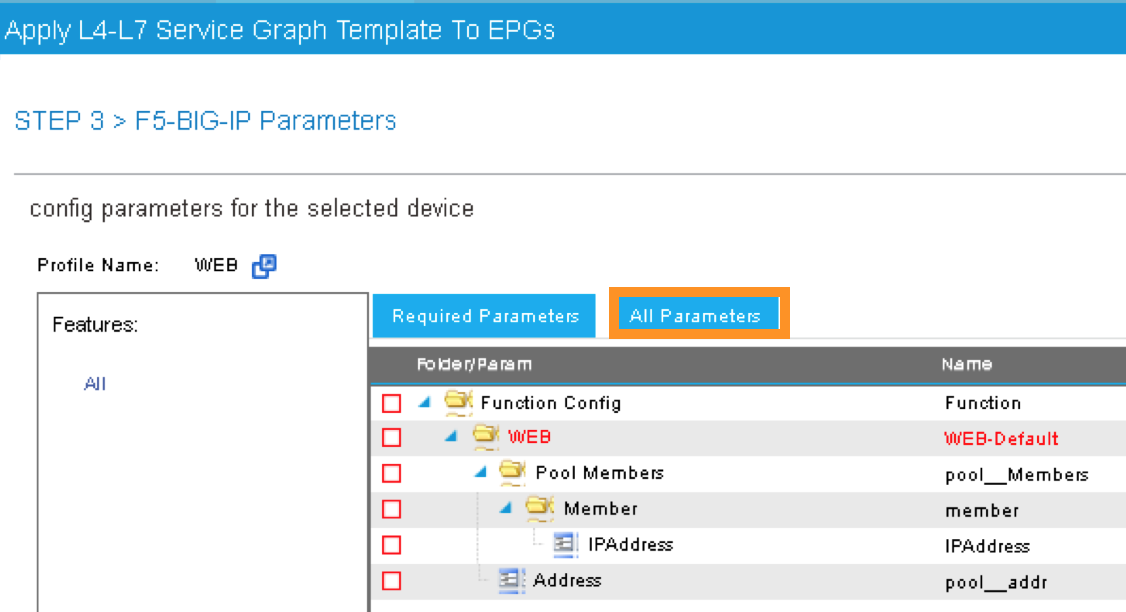
Once you click the All Parameters tab, the folder and parameters will appear. To edit the parameter, you need to expand the parameter by clicking the > and double the field to change the parameter’s name and value. Let us edit the following parameters:
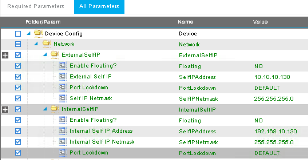
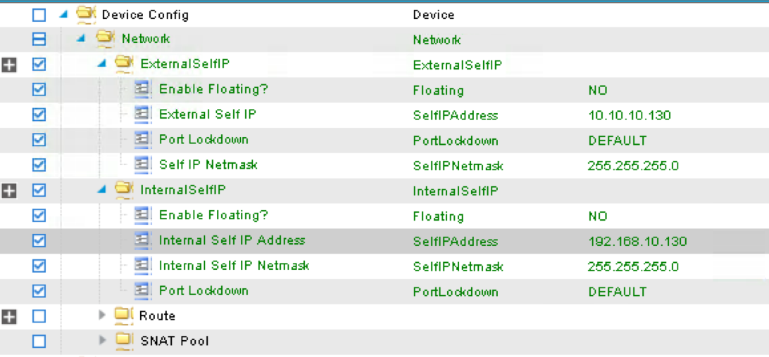
Under Device Config
Press > to expand the Network configuration folder
Press > to expand the folder ExternalSelfIP
Double click the parameter Enable Floating? and select No as the value
Click UPDATE to apply
Double click the parameter External Self IP Address and enter 10.10.10.130 as the value
Click UPDATE to apply
Double click the parameter External Self IP Netmask and enter 255.255.255.0 as the value
Click UPDATE to apply
Double click the parameter Port Lockdown and select Default as the value
Click UPDATE to apply
Press > to expand the folder InternalSelfIP
Double click the parameter Enable Floating? and select No as the value
Click UPDATE to apply
Double click the parameter Internal Self IP Address and enter 192.168.10.130 as the value
Click UPDATE to apply
Double click the parameter Internal Self IP Netmask and enter 255.255.255.0 as the value
Click UPDATE to apply
Double click the parameter Port Lockdown and select Default as the value
Click UPDATE to apply
Device config is BIG-IP device level configuration, like self-IP and default route. Resource configured in the device config will be used by Function Config
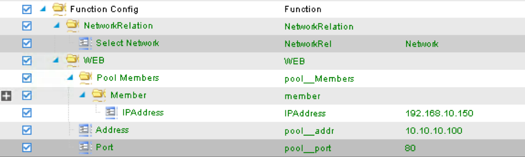
Assign Device Config “Network” to Function Config “NetworkRelation”
Note
It is extremely important to assign Network to NetworkRelation, fail to perform this step will result in graph deployment failure, as there will not be any network resource associated with the graph

The above step associates the network information under device config to the BIG-IP virtual server.
Apply at deployment WEB service graph configuration under Function Config
Press > to expand the WEB configuration folder
Double click on the name and delete Default
Click UPDATE to apply
Press > to expand the Pool Members folder
Press > to expand the Member folder
Double click to enter value into the IPAddress field: 192.168.10.150
Click UPDATE to apply
Back to the WEB configuration folder
Double click to enter value into the Address field (pool__addr):
10.10.10.100
Click UPDATE to apply
Double click the parameter Port field (pool__port): 80
Click UPDATE to apply

Function config is BIG-IP virtual server level configuration. We define the WEB service catalog parameters here, as well as associating the device level network config to this virtual server.
Make sure both the device config and function config are correct
Device Config
Function Config
Click “FINISH” to deploy the graph
2.2.18. APIC – Verifying WEB application deployment
APIC: Verifying the service graph deployment
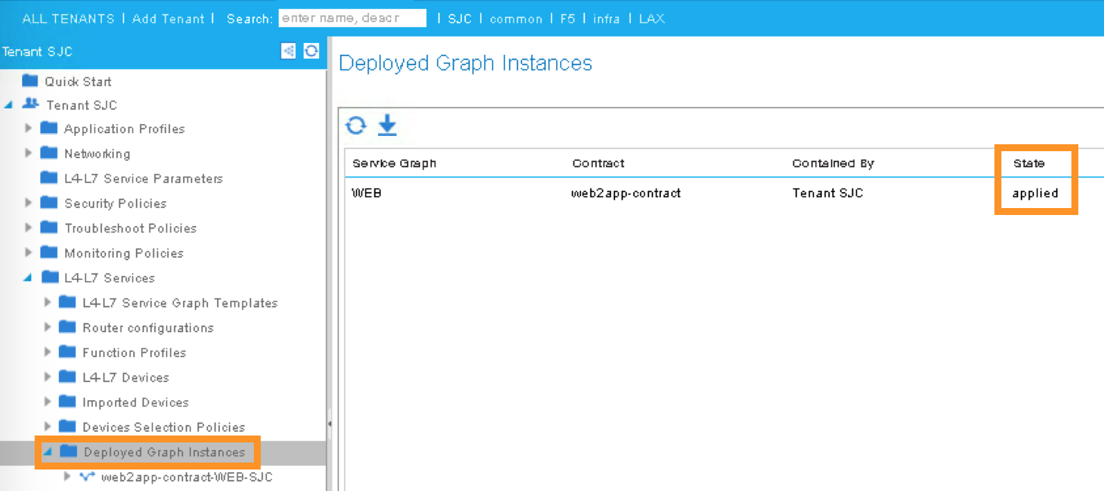
You can now verify if APIC has deployed the service graph correctly. First, navigate the following:
Tenant SJC -> L4-L7 Services -> Deployed Graph Instances
You should be able to see a screen similar to the following. The State should say “applied”
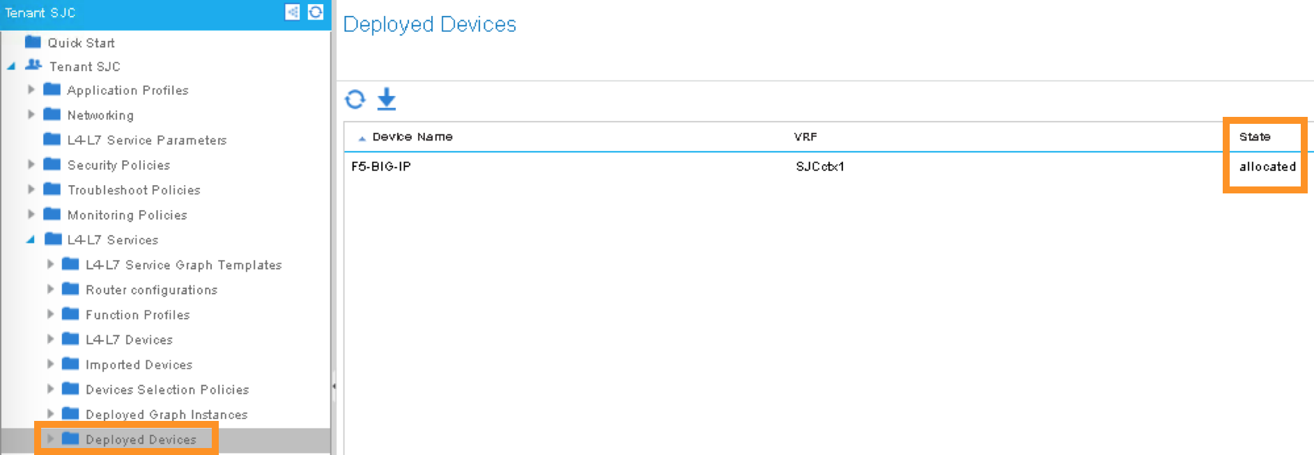
Tenant SJC -> L4-L7 Services -> Deployed Devices
You should be able to see a screen similar to the following. The State should say “allocated”
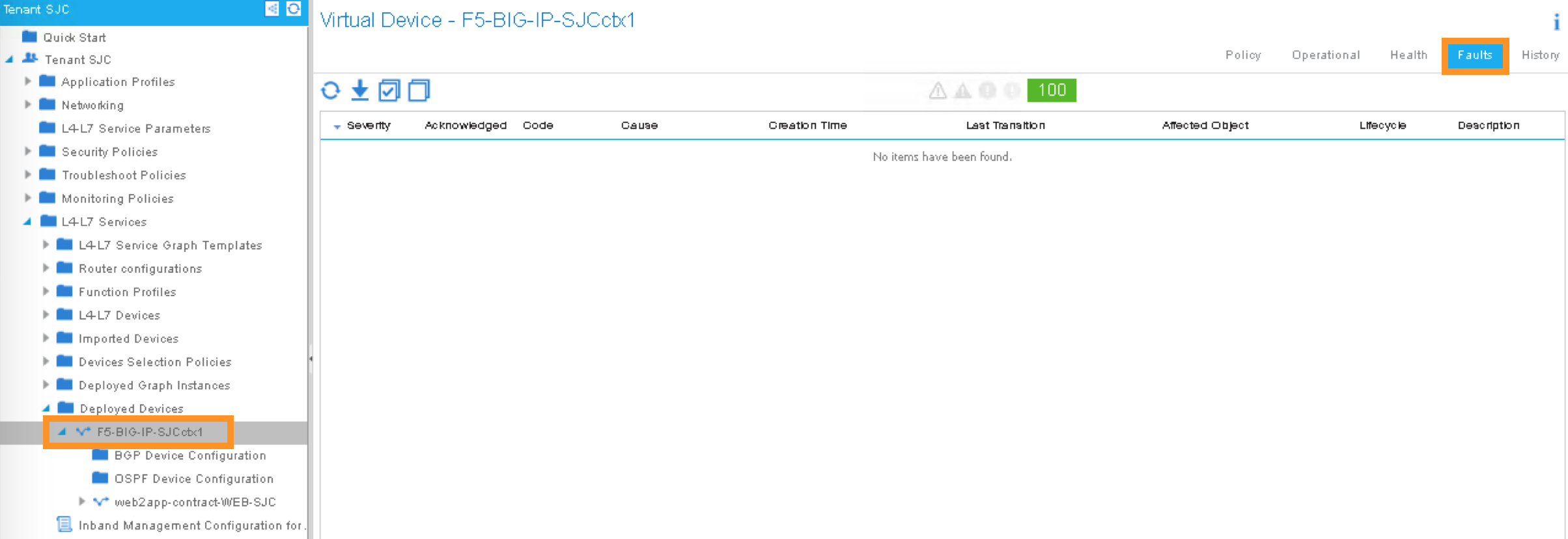
Make sure there is no faults to the deployment:
2.2.19. iWorkflow – Verifying the template deployment
Once the service graph is deployed in Cisco APIC, administrator can also view application status in F5 iWorkflow.
Log into the F5 iWorkflow 198.18.128.135 with the following username and password from the web browser (if the previous session has timed out):
iWorkflow: https://198.18.128.135
Username: admin
Password: C1sco12345
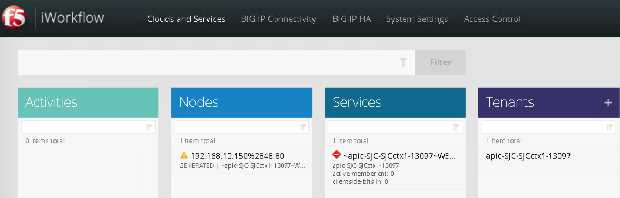
Under the iWorkflow Cloud and Services. In the Work pane, under:
Services: graph deployment status
Tenant: APIC tenant information
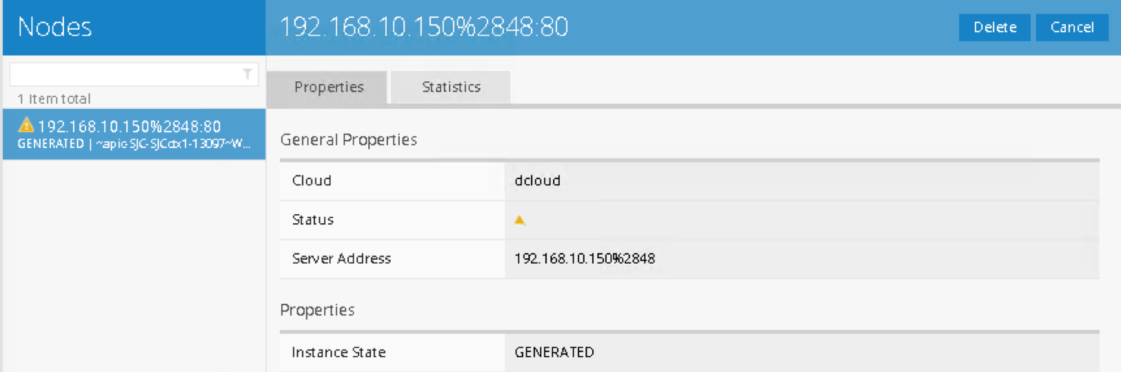
Nodes: pool members information
Notice the graph is “unhealthy” because no servers are available to the BIG-IP virtual server. This is expected because dCloud only validate control plane, as a result, BIG-IP data plane validation to the servers failed.
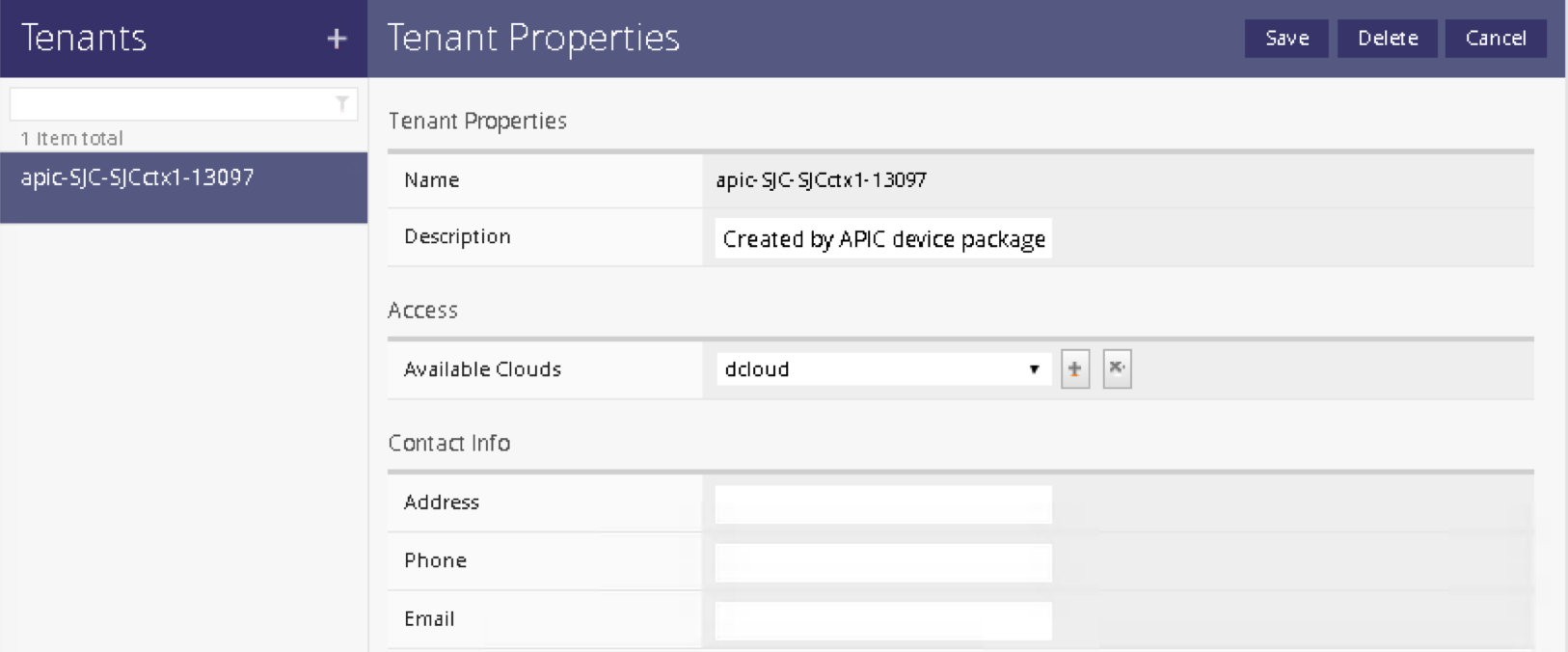
Tenants:
Services
Notices “Customize Application Template” contains the fields visible in APIC. User input the values from APIC.
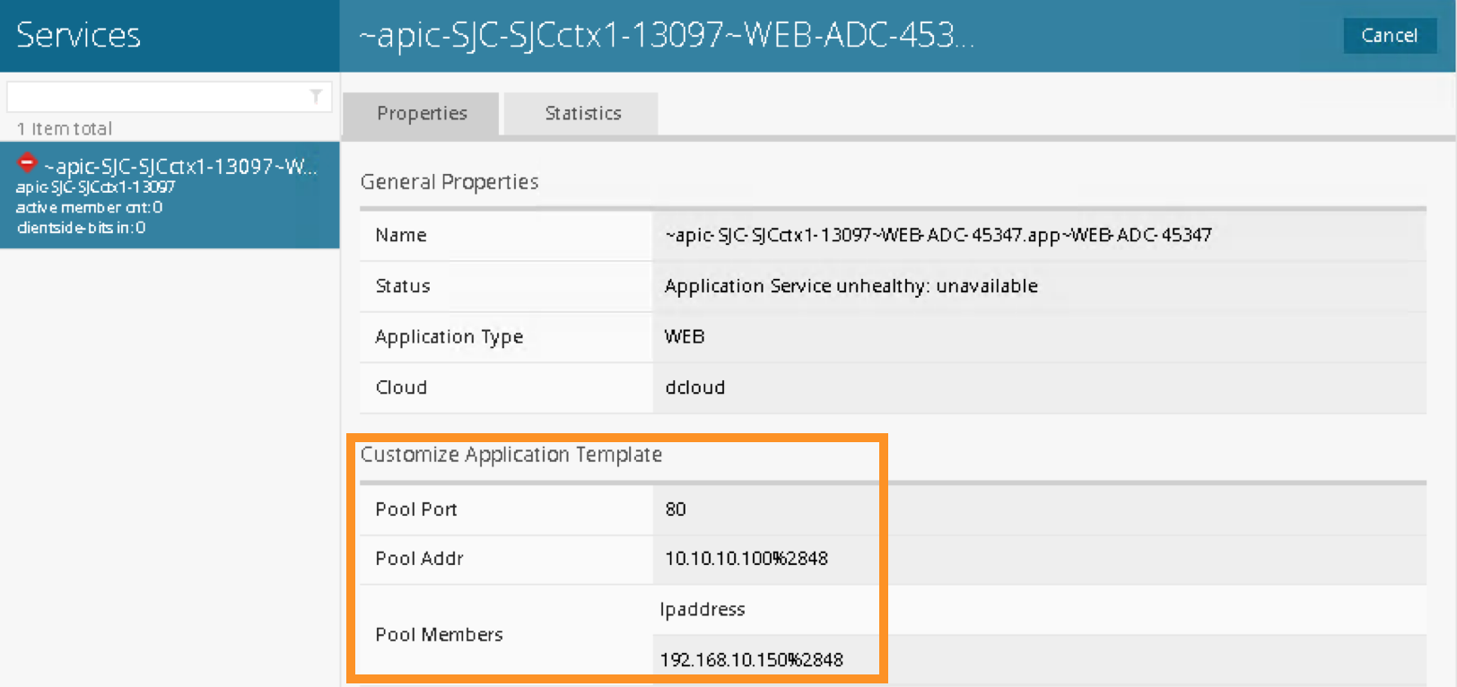
In case Customize Application Template is empty, please check back in a few minutes until the resource is refresh
Nodes:
This the member IP entered through APIC.
2.2.20. BIG-IP – Verifying Application Services (Virtual Server) deployment
Log into the F5 BIG-IP 198.18.128.130 with the following username and
password from the web browser (if the previous session has timed out):
BIG-IP: https://198.18.128.130
Username: admin
Password: C1sco12345
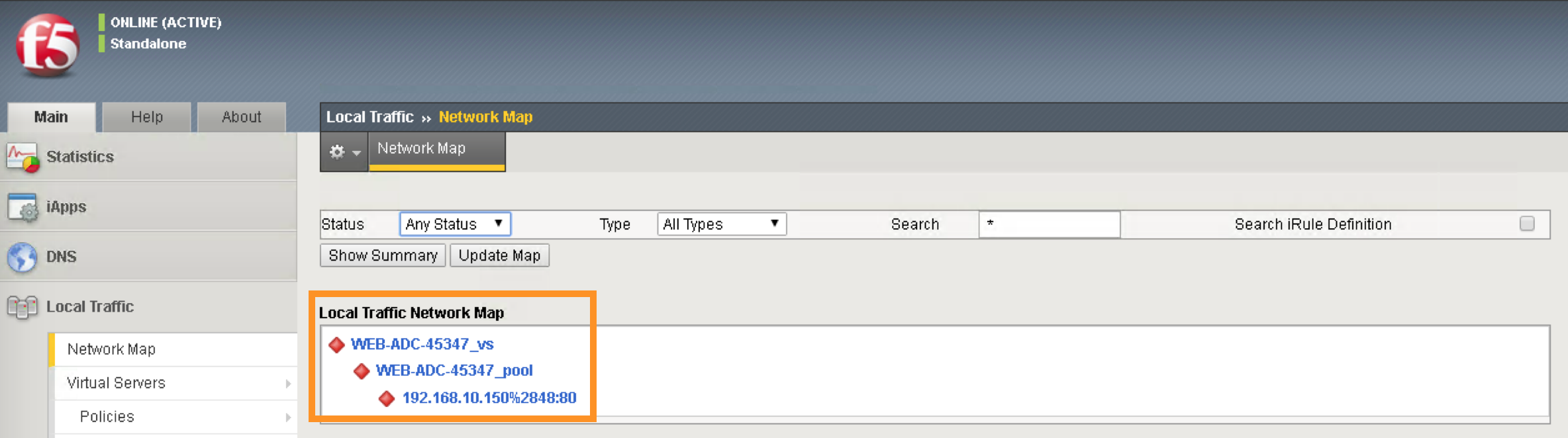
On the Main menu, click Local Traffic -> Network Map. Then on the top right corner, next to the Log out button, click the drop down to select the newly created Partition (please note that this reflects the APIC Virtual Device ID):

Once you are in the partition, click Local Traffic -> Network Map. You should be able to see the virtual server is configured along with its pool and pool members.
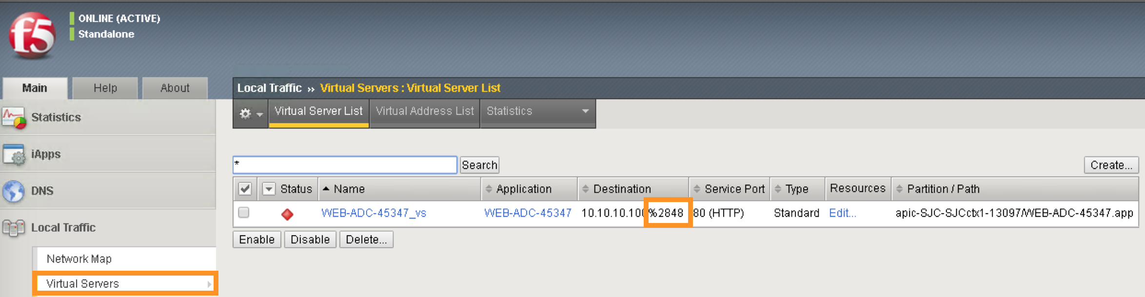
On the right Navigation menu, click the Local Traffic -> Virtual Servers
and you should be able to see the brief Virtual IP information. You can
see that the VIP is currently listening on HTTP port 80.
The number (in this example, 2848) after the % mark represents the route domain (RD) number. There will be a RD number assign to each APIC partition, which equivalent to an ACI L3 VRF. This allows BIG-IP to provide multi-tenancy support in ACI environment.
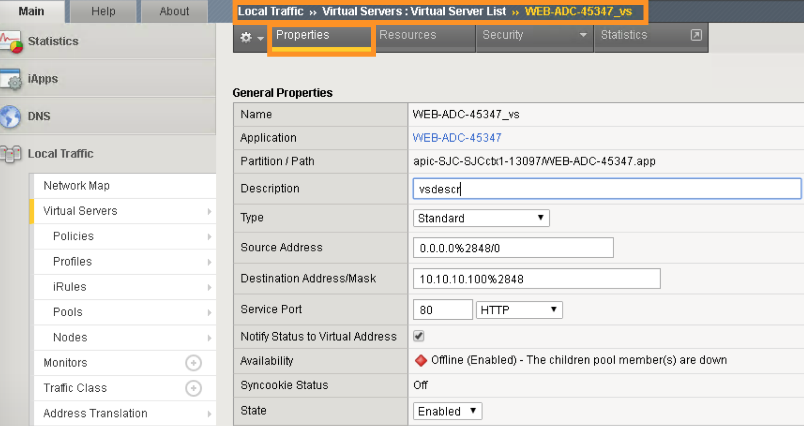
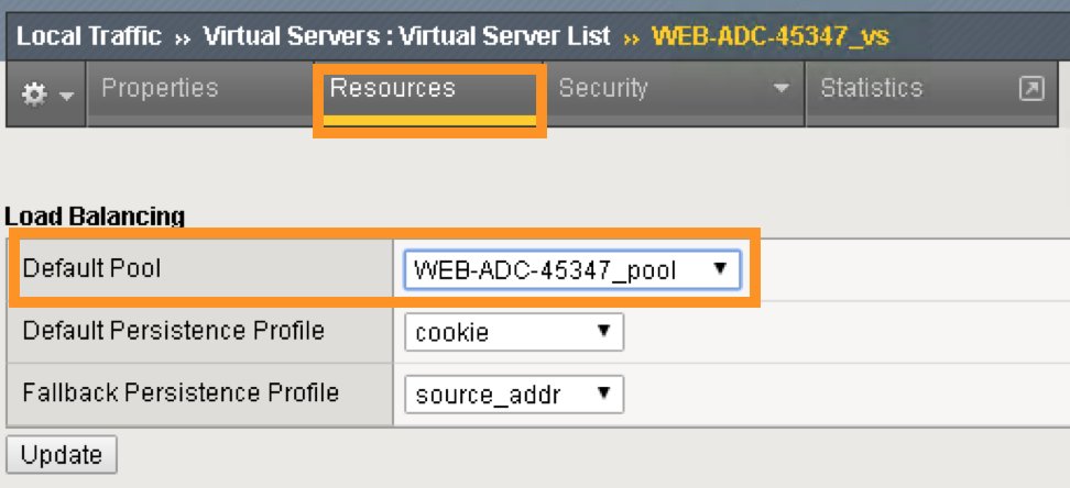
In the Virtual Server List, click the Name in the hyperlink and you will see the Property of the Virtual Server with more detailed information. The configured the parameters will appear here.
Click on “Resource”, notice the pool name being used
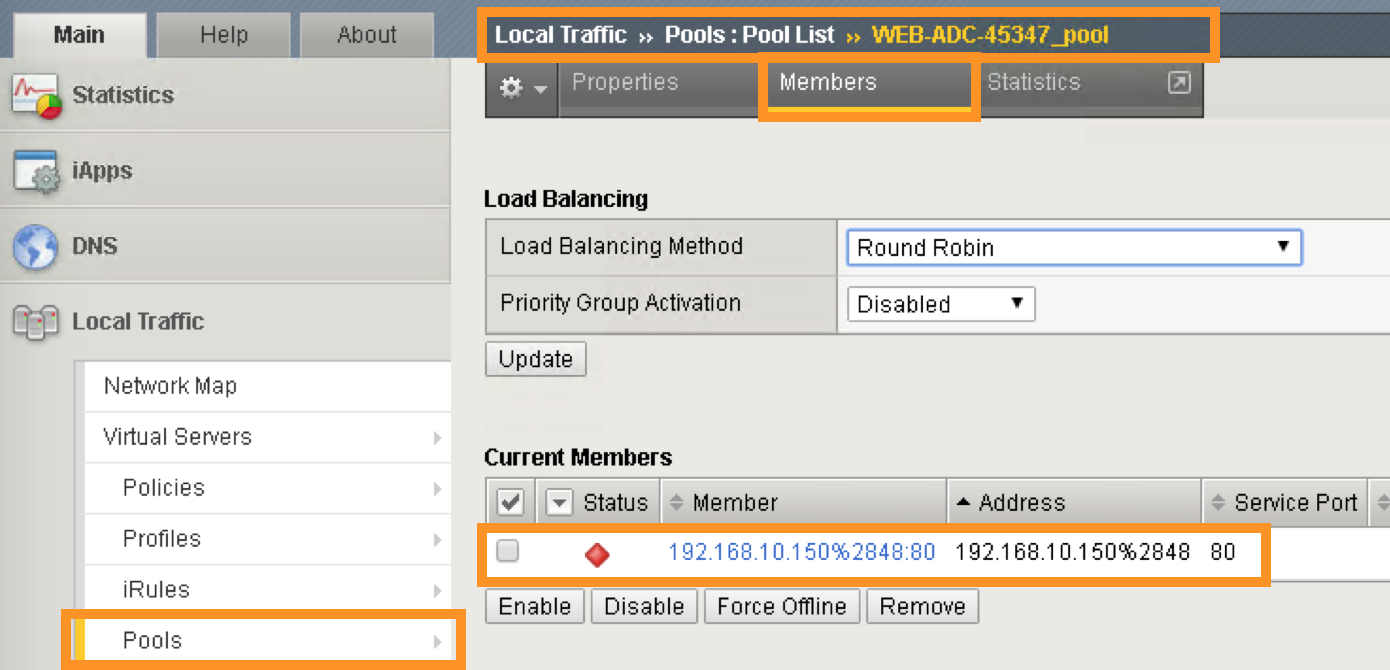
Click Local Traffic -> Pools and you should see the brief information of the real server pool information:
Go back to the Navigation pane and click the iApps -> Application Services. Notice the name of the Application Services is same as the Services name in iWorkflow.
Template is the iApps template that associated with this application service
Partition/Path is the APIC created partition and the name of the application service
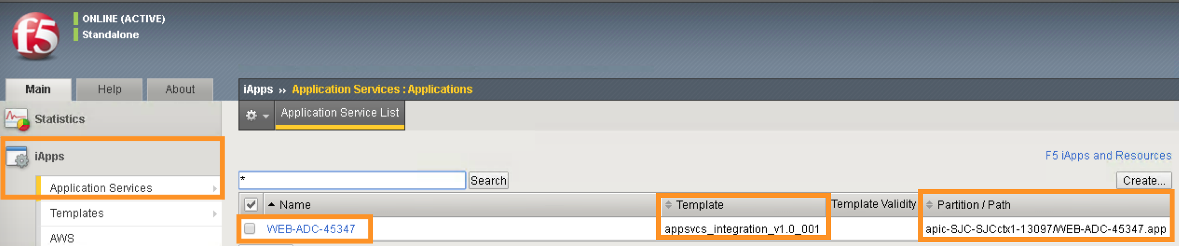
F5 iWorkflow service name
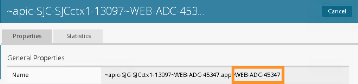
Click the application service name will direct to the Application Services Components. By using iApps template, you can configure a full features virtual server by specifying customized parameters exposed to APIC. Only the highlighted ones are entered by APIC, the rest of the virtual servers features are built inside the iApps template.
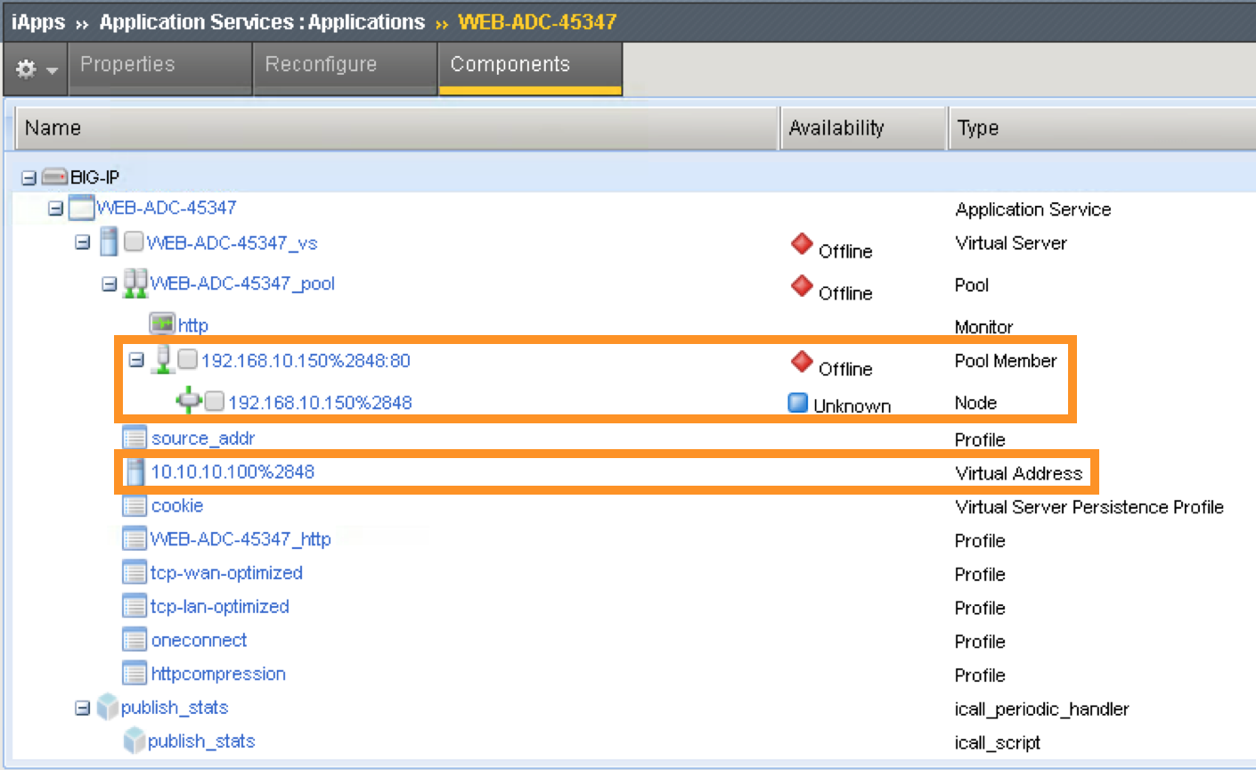
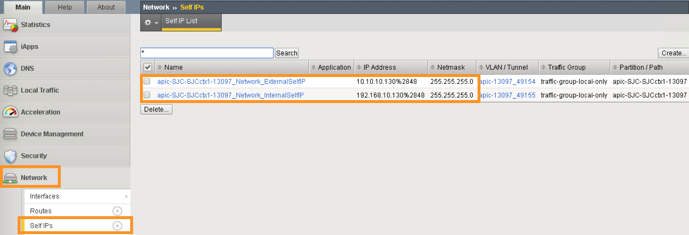
Network -> Self IP configuration from APIC
VLAN information imported from APIC:
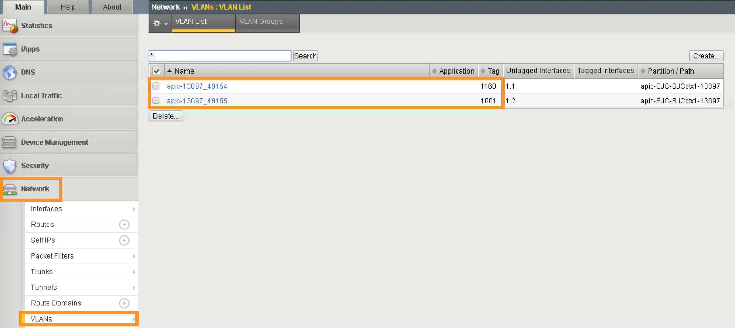
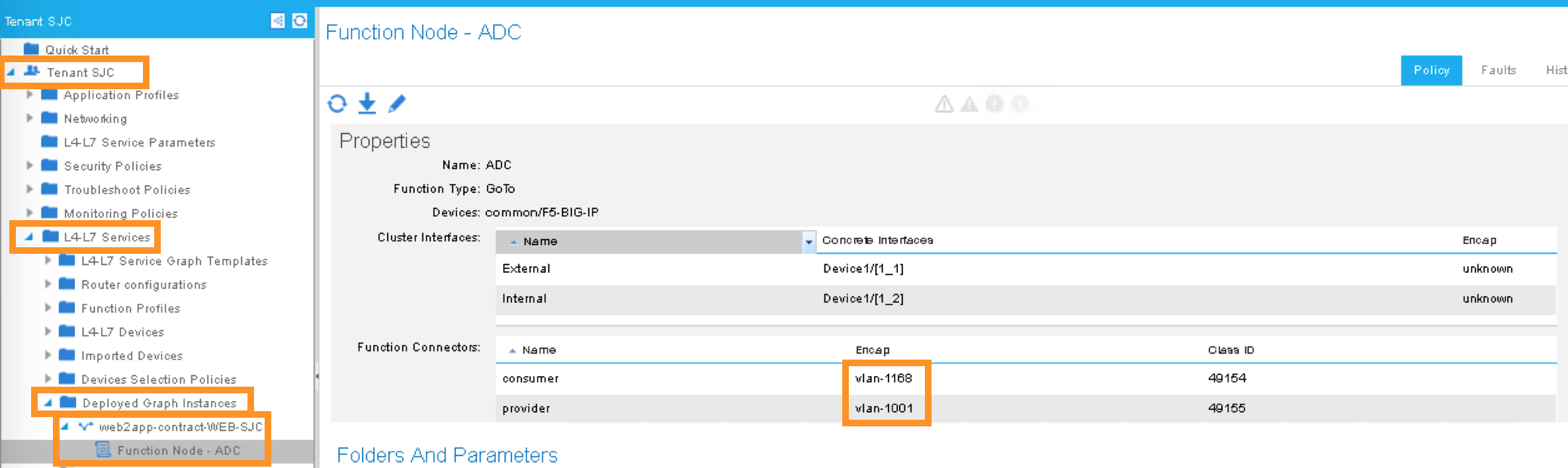
Same VLAN tags are being assigned in APIC
This concludes Scenario 1 “Deploy Service Graphs in Cisco ACI using F5 iWorkflow” lab.